The
Peak
Adjust
Circuit
The trim pot in this circuit oniy has
a
very small range,
%
dB.
It
is
for final high end adjustment. The frequency
to send in
is
18 kHz, record the tone
at
"O
VU" in, switch
to MONITOR and
read the result. Adjust trim pot
#l
1
R109, to read
"O
VU" in playback.
Both of the record equalization circuits
have rather
a
small range of adjustment. The high frequency adjust
is
3 dB, the peak adjust
is
%
dB. If you can't seem to get
a
"good" reading because you run out of adjustment range,
check these
3
points.
The "Record adjust" (point #9 in this review). Re-do,
send in
"O
VU"
at
1 kHz. Record the tone and read
playback. If
it
is
low, it will be impossible to get
15 kHz or 18 kHz up to
"O
VU." Reset and try again.
Still no good? Re-check the bias. If the bias current
is
too high, the high frequency sensitivity
is
reduced in
relation to the 1
kHz point. Check it out.
Switch the 80-8
to INPUT and send in
a
signal of 1 kHz
at
a
level of 1 volt
(O
dB,
+l
0 VU). Adjust the trim pot
#
12
R106.
22
k0hms until the LED goes on.
We suggest that you do this LED adjustment
as
rapidly
as
possible. +l0 VU
is
not good for the meter movement.
More than one minute of operation
at
+l0 may damage
the armature, so set everything up before applying the
signal and be brief.
With the 80-8
al1 buttoned up and the service door closed
you
can now check the Signal to Noise of the whole
system. You use the big test meter. Record with no input
signal and
read the result. The reading should be -60 dB
or better (un-weighted).
That's it. The whole procedure for an electronic overhaul
of the 80-8. Mechanical adjustments such
as
brake and
holdback torque,
ree1 height adjust and wow and flutter
measurements must be
done first, but they are major
service and should not be necessary "out of the box." The
transport logic
contro1 and switching system are described
in the
service manual.
We'll sell you
a
copy if you want one, but digital i.c.
theory
is
very complex and the necessary test equipment
for repairs costs more than the recorder. The
service
manual
is
not written
as
a
guide to the beginner, so be
advised,
it
may not help your understanding of the 80-8.
It is useful only to the experienced maintenance technician.
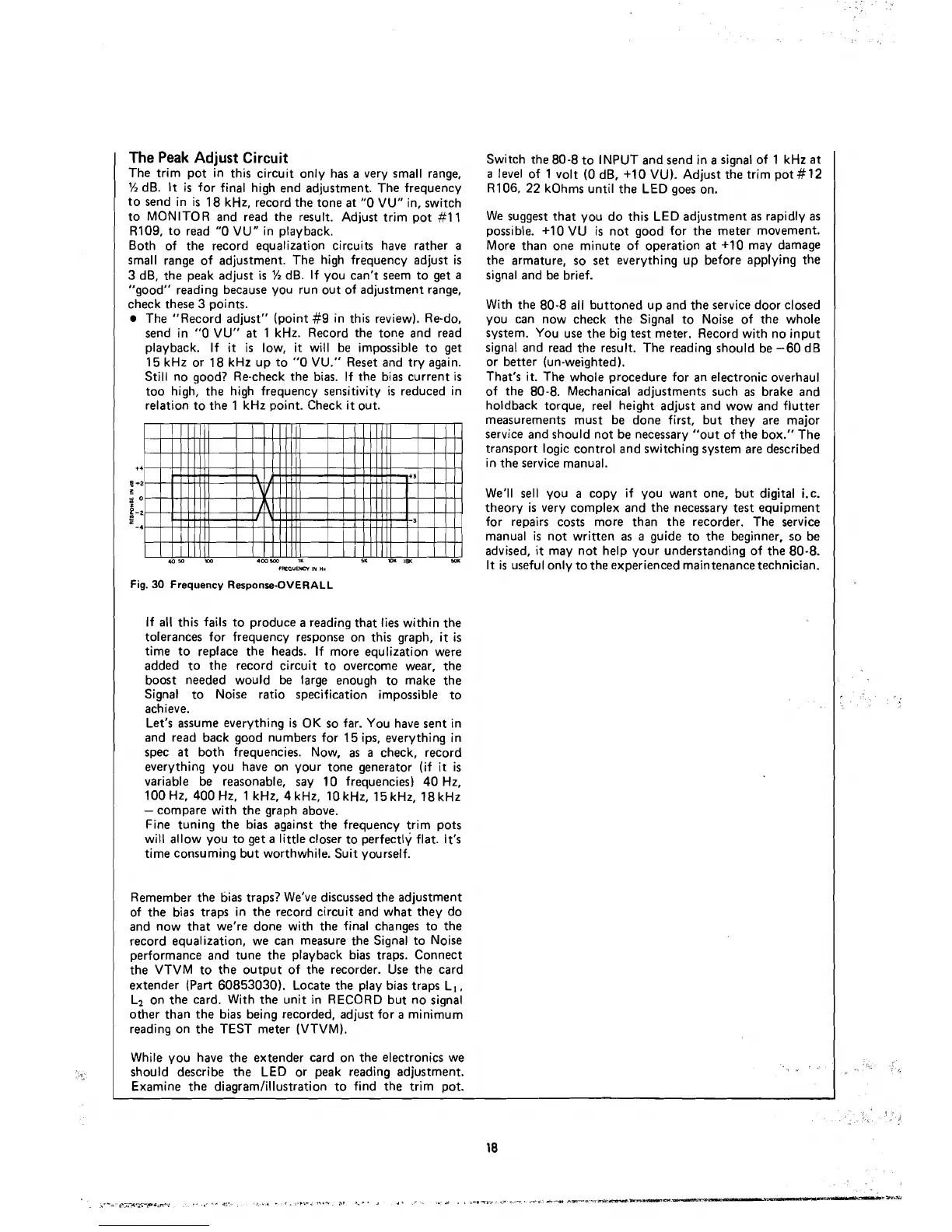
Fig.
30
Frequency Response-OVERALL
If
al1
this fails to produce
a
reading that lies within the
tolerances for frequency response on this graph,
it
is
time to replace the heads. If more equlization were
added to the record circuit to overcome wear, the
boost
needed would be large enough to make the
Signal to
Noise ratio specification impossible to
achieve.
Let's assume everything
is
OK so far. You have sent in
and
read back good numbers for 15 ips, everything in
spec
at
both frequencies. Now,
as
a
check, record
everything you
have on your tone generator (if
it
is
variable be reasonable, say 10 frequencies) 40 Hz,
100 Hz, 400 Hz, 1
kHz, 4 kHz, 10 kHz, 15 kHz, 18 kHz
-
compare with the graph above.
Fine tuning the bias against the frequency trim pots
will allow you to get
a
little closer to perfectly flat. It's
time consuming but worthwhile. Suit yourself.
Remember the
tjias traps? We've discussed the adjustment
of the bias traps in the record circuit and what they do
and now that we're
done with the final changes to the
record equalization, we
can measure the Signal to Noise
performance and tune the playback bias traps. Connect
the VTVM to the output of the recorder. Use the card
extender (Part 60853030). Locate the play bias traps L,,
Li on the card. With the unit in RECORD but no signal
other than the bias being recorded, adjust for
a
minimum
reading on the TEST meter (VTVM).
While you
have the extender card on the electronics we
should describe the LED or peak reading adjustment.
Examine the diagramlillustration to find the trim pot.