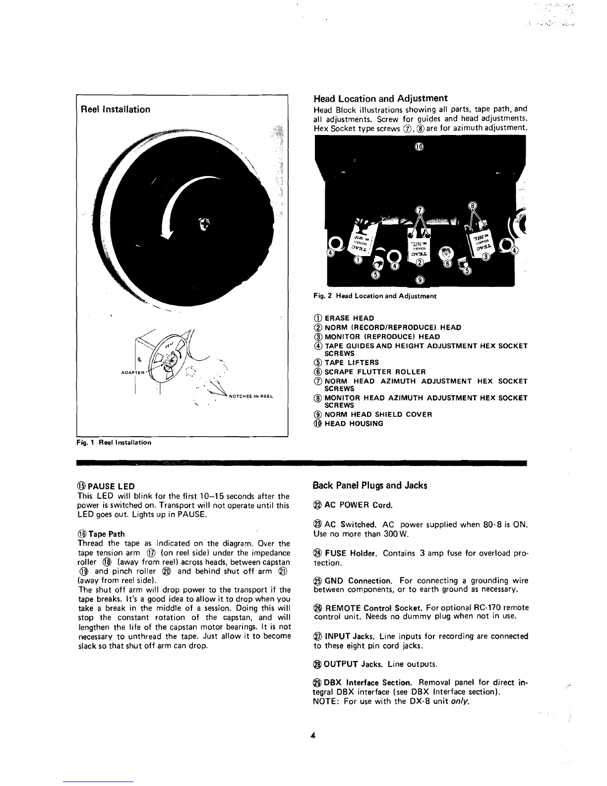
Reel
Installation
s
Fig.
1
Reel lnstallation
@PAUSE
LED
This LED will blink for the first
10-15
seconds after the
power is switched on. Transport will not operate until this
LED goes out. Lights up in PAUSE.
@
Tape Path
Thread the tape
as
indicated on the diagram. Over the
tape tension arm
@
(on ree1 side) under the impedance
roller
@
(away from reel) across heads, between capstan
@
and pinch roller
@l
and behind shut off arm
@
(away from ree1 side).
The shut off arm will drop power to the transport if the
tape breaks.
It's
a good idea to allow it to drop when you
take a break in the middle of a session. Doing this will
stop the constant rotation of the capstan, and will
lengthen the life of the capstan
motor bearings.
It
is not
necessary to unthread the tape. Just allow
it
to become
slack so that shut off arm
can drop.
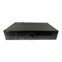
Head
Location
and
Adjustment
Head Block illustrations showing al1 parts, tape path, and
al1
adjustments. Screw for guides and head adjustments.
Hex ~ocket tvpe screws
0,
hare for azimuth adjustment.
Fig.
2
Head Location and Adjustment
@
ERASE HEAD
@
NORM (RECORDIREPRODUCE) HEAD
@
MONITOR (REPRODUCE) HEAD
@
TAPE GUIDESAND HEIGHT ADJUSTMENT HEX SOCKET
SCREWS
@
TAPE LIFTERS
@
SCRAPE FLUTTER ROLLER
@
NORM HEAD AZIMUTH ADJUSTMENT HEX SOCKET
SCREWS
@
MONITOR HEAD AZIMUTH ADJUSTMENT HEX SOCKET
SC
R EWS
@
NORM HEAD SHIELD COVER
@
HEAD HOUSING
6ack
Panel
Plugs
and
Jacks
@
AC POWER Cord.
@$
AC Switched. AC power supplied when 80-8
is
ON.
Use no more than 300
W.
@
FUSE Holder. Contains
3
amp fuse for overload pro-
tection.
@
GND Connection. For connecting
a
grounding wire
between components, or to earth ground
as
necessary.
@
REMOTE Control Socket. For optional RC-170 remote
contro1 unit. Needs no dummy plug when not in use.
@
INPUT Jacks. Line inputs for recording are connected
to these eight pin cord jacks.
@
OUTPUT Jacks. Line outputs.
@
DBX
Interface Section. Removal panel for direct
in-
tegral DBX interface (see DBX Interface section).
NOTE: For use with the DX-8 unit
only.