CONNECTION AND OPERATION OF
THE
DX-8
Hook-up.
(see Fig.
31
1.
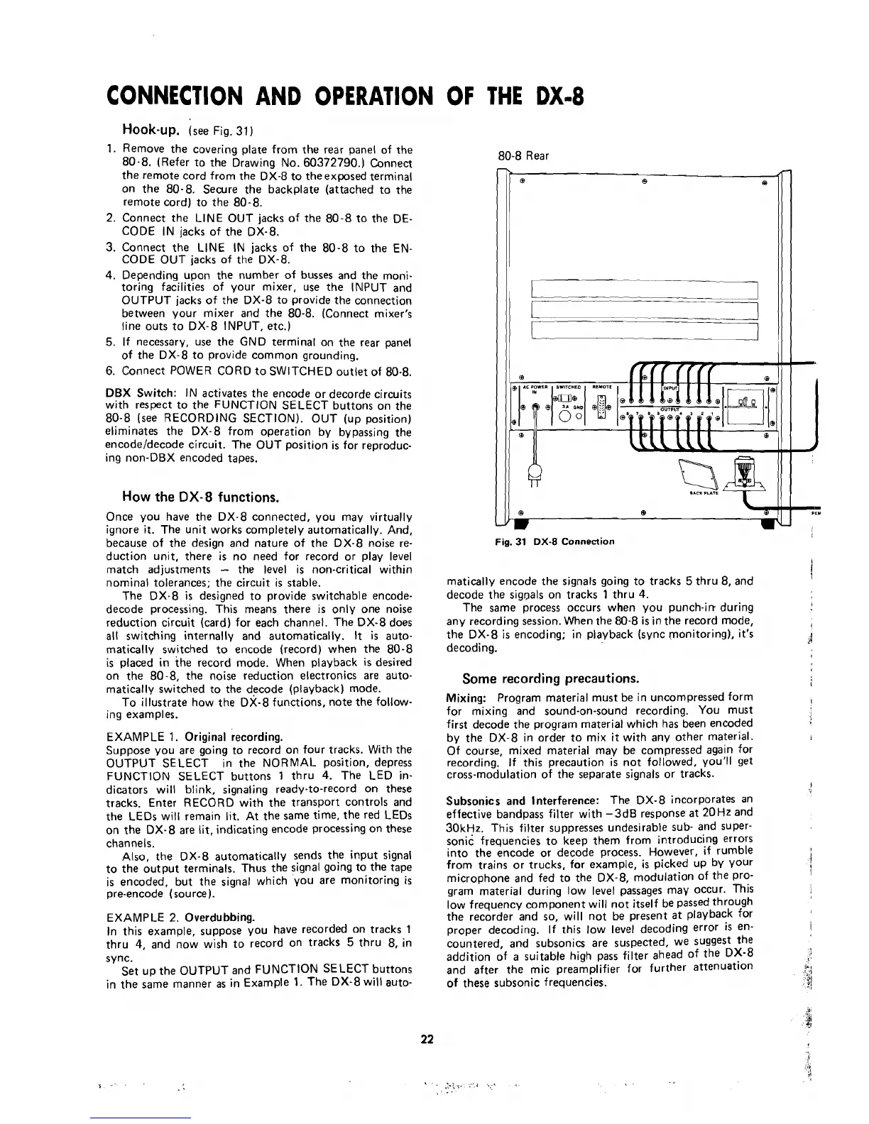
Remove the covering plate from the rear panel of the
80-8. (Refer to the Drawing No. 60372790.) Connect
the remote cord from the DX-8 to theexposed terminai
on the 80-8.
Secure the backplate (attached to the
remote cord) to the
80-8.
2. Connect the LINE OUT jacks of the 80-8 to the DE-
CODE IN jacks of the DX-8.
3.
Connect the LINE
IN jacks of the 80-8 to the EN-
CODE OUT jacks of the DX-8.
4.
Depending upon the number of busses and the moni-
toring facilities of your mixer, use the IMPUT and
OUTPUT jacks of the DX-8 to
provide the connection
between your mixer and the
80-8. (Connect mixer's
line outs to DX-8 INPUT, etc.)
5.
If necessary, use the GND terminal on the rear panel
of the DX-8 to
provide common grounding.
6. Connect POWER CORD to SWITCHED outlet of
80-8.
DBX Switch: IN activates the encode or decorde circuits
with respect to the FUNCTION SELECT buttons on the
80-8 (see RECORDING
SECTIONI. OUT (up position)
eliminates the DX-8 from
operation by bypassing the
encodeldecode circuit. The OUT position
is
for reproduc-
ing non-DBX encoded tapes.
How the
DX-8
functions.
Once you have the DX-8 connected, you may virtually
ignore it. The unit works completely automatically. And,
because of the design and nature of the DX-8
noise re-
duction unit, there is no
need for record or play level
match adjustments
-
the level is non-critica1 within
nomina1 tolerances; the circuit
is
stable.
The DX-8
is
designed to provide switchable encode-
decode processing. This means there
is
only one noise
reduction circuit (card) for each channel. The DX-8 does
al1
switching internally and automatically.
It
is
auto-
matically switched to encode (record) when the 80-8
is
placed in the record mode. When playback
is
desired
on the
80-8, the noise reduction electronics are auto-
matically switched to the decode (playback) mode.
To illustrate how the
DX-8 functions, note the follow-
ing examples.
EXAMPLE
1.
Original recording.
Suppose you are going to record on four tracks. With the
OUTPUT SELECT in the NORMAL position, depress
FUNCTION SELECT buttons
1
thru
4.
The LED in-
dicators will blink,
signaling ready-to-record on these
tracks. Enter RECORD with the transport controls and
the LEDs will
remain lit. At the same time, the red LEDs
on the DX-8 are
lit,
indicating encode processing on these
channels.
Also, the DX-8 automatically sends the input signal
to the output
terminals. Thus the signal going to the tape
is encoded, but the signal which
you are monitoring
is
pre-encode (source).
EXAMPLE 2. Overdubbing.
In this example, suppose you have recorded on tracks
1
thru
4,
and now wish to record on tracks
5
thru 8, in
s
ync.
Set
up the OUTPUT and FUNCTION SELECT buttons
in the
same manner
as
in Example
1.
The DX-8 will auto-
80-8 Rear
Fig.
31
DX-8
Connection
rnatically encode the signals going to tracks
5
thru 8, and
i
decode the sigpals on tracks
1
thru
4.
The same process occurs when you punch-irr during
any recording session. When the 80-8
is
in the record mode,
t
the DX-8
is
encoding; in playback (sync monitoring), it's
decoding.
d
Some
recording precautions.
,
Mixing: Program materia1 must be in uncompressed form
I
for mixing and sound-on-sound recording. You must
first decode the program material which has been encoded
by the DX-8 in
order to mix it with any other material.
I
Of course, mixed material may be compressed again for
recording.
If this precaution
is
not followed, you'll
get
cross-modulation of the separate signals or tracks.
l
Subsonics and lnterference: The DX-8 incorporates an
effective bandpass filter with
-
3dB response
at
20 Hz and
30kHz. This filter suppresses undesirable sub- and super-
sonic frequencies to keep them from introducing errors
into the encode or decode process. However,
if rumble
from trains or trucks, for example,
is
picked up by your
j
microphone and fed to the DX-8, modulation of the Pro-
l
gram materia1 during low ievei passages may occur. This
low frequency component will
not itself be passed through
the recorder and so, will
not be present at playback for
proper decoding. If this low leve1 decoding error
iS
en-
l
countered, and subsonics are suspected, we suggest the
addition of
a
suitable high pass filter ahead of the DX-8
and after the mic preamplifier for further attenuation
I
,
'
of
these subsonic frequencies.
:/