AInstallation
C
Ref. DCD01/3074 - XF510Cr-Sr-Dr_en_C
22/31
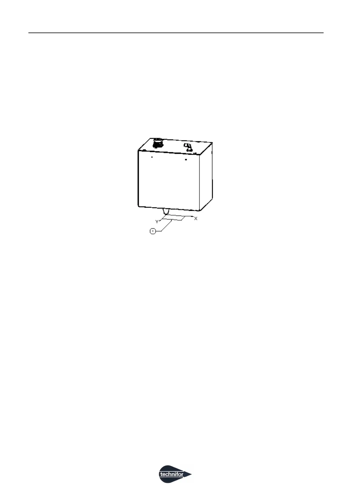
2. Coordinate system
The coordinate system used in our machines is shown in the following diagram.
The Z axis is the vertical position. This axis is used to manually adjust the height of the stylus for marking parts of
different sizes.
When a marking cycle is launched, the stylus always begins at the origin point and returns to the origin at the end
of the cycle.
Coordinate system
1 : XF510Cr: marking area: 40 mm (1.575 in) x 50 mm (1.969 in)
2 : XF510Sr: marking area: 80 mm (3.15 in) x 50 mm (1.969 in)
3 : XF510Dr: Marking area: 160 mm (6.299 in) x 50 mm (1.969 in)
3. Compressed air supply
Connect the compressed air supply, located near the work station, to the air regulator filter inlet.
No tools are needed to connect and disconnect the air tubes. To make the connection, insert the Ø 6 mm
(0.236 in) tube into the connector until it stops. To disconnect the tube from the air supply, press the clamping ring
and pull the tube out of the connector.
Operating pressure: 1 Bar (14.504 PSI) to 8 Bar (116.03 PSI)
 Loading...