C
Ref. DCD01/3074 - XF510Cr-Sr-Dr_en_C
15/31
CInstallation
1. Installation
Mounting
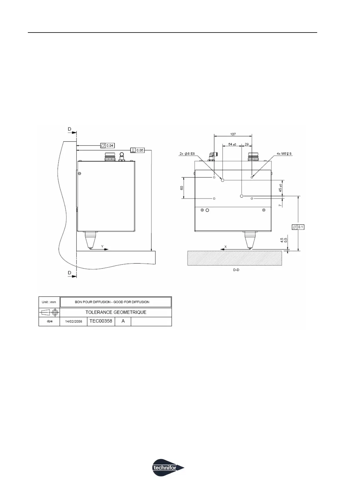
Attach the XF510Cr/Sr/Dr integrable marking head to a support using 4 M6 bolts.
The screws must penetrate 8 mm (0.315 in) [0 +2 mm] deep into the casing (risk of blocking the X carriage if the
screws are too long, risk of stipping the threads if they are too short).
Torque is 8.3 Nm (6.119 lb ft) maximum (class 8.8 screw).
Only the back side of the XF510Cr/Sr/Dr integrable head should be attached for mounting.
To obtain a uniform mark over the whole marking surface, mount the head so that it is parallel to the surface to be
marked.
For alignment, there are positioning holes Ø 8E8 for Ø 8 mm (0.315 in) pin.
When positioning the head vertically, leave a 5 mm (0.197 in) space to facilitate disassembly or vertical
adjustment of the stylus.
To facilitate adjustment, Technifor can provide a height adjustment system.
 Loading...