Network Meter Block Installation, Operation, & Maintenance Manual
Monitoring and Configuring the NMB 39
4.5.1.2 Alarm Severity
The NMB provides five severity levels for meter alarms, level 1 being the most serious and level 3 being
the least. The following table provides a description of each severity level:
4.5.2 Resetting Alarms in the NMB’s Web Interface
In the NMB web interface’s configuration area, each alarm displays or for the both the alarm buffer
and the alarm latch. The alarm latch indicates that the alarm’s condition occurred and must be manually
reset, even if the meter’s operation has since returned to be within acceptable ranges. An alarm remains
latched until you acknowledge it, regardless of whether the meter has returned to working within normal
thresholds.
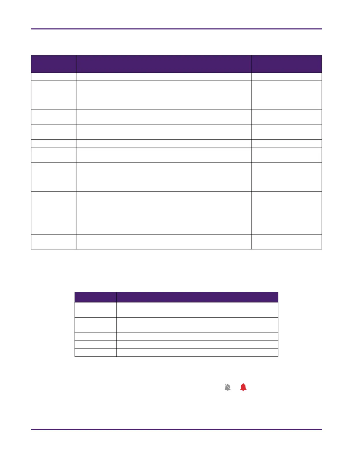
Table 3: List of Alarms
Alarm Name Meaning
Location in Web
Interface
All Meters
Pulse Security
Alarm
The NMB detects missing pulses in the meter’s pulse sequence
when Pulse Input Mode is set to Dual. The NMB identifies an error
in the A-B or B-A pulse sequencing indicative of hardware or wiring
failure.
Dashboard and
Meter > Status
Low Flow The calculated flow rate is below the meter’s configured minimum
flow rate.
Dashboard and
Meter > Status
High Flow A batch’s instantaneous flow rate is greater than the meter’s config-
ured maximum flow rate.
Dashboard and
Meter > Status
Turbine Meters
Wrong Setup A configuration parameter for the turbine meter is improperly set
and the NMB cannot function as configured.
Turbine Diagnostics >
Status
Bent Blade The calculated blade average deviation percentage is greater than
the turbine meter’s configured maximum value and the calculated
blade maximum deviation percentage is greater than the turbine
meter’s configured maximum value.
Turbine Diagnostics >
Status
Non-Uniform
Flow
The calculated bearing average deviation percentage is greater
than the turbine meter’s configured maximum value and the calcu-
lated bearing maximum deviation percentage is greater than the tur-
bine meter’s maximum or the calculated consistency integral
(Integral Deviation %) is greater than the entered maximum error
value for consistency integral.
Turbine Diagnostics >
Status
Bearing The calculated bearing ratio deviation percentage is greater than the
turbine meter’s configured maximum.
Turbine Diagnostics >
Status
Table 4: Alarm Severity Levels
Level Description
1 Complete outage or degradation so severe that core function-
ality is unusable
2 Functional degradation for a subset of members or a loss of
some core functionality for all members
3 Noticeable degradation or loss of minor functionality
4 Loss of redundancy or capacity; no member-visible impact
5 Any other minor issues