3. Remove the (interlocked) side covering from the lower part of the upright, on the outer side
of the equipment.
4. Remove the guard located under the side covering.
5. Remove the front guard.
6. Remove the right-hand front side guard.
7. Remove the brake assembly ange and cam. Remove the brake cable from its housing.
8. Remove the brake.
The stop screw is positioned correctly if the screw touches the frame slightly when pulling
the lever all the way back. This means that the screw is resting up against the frame, with
less than one 180° degree turn to fully tighten it.
7.7. 4 DISASSEMBLY OF BRAKE DISC/ RPM SENSOR/ FRONT PULLEY
1. Disassemble the brake as explained in paragraph “7.7.3 Dismantling the BRAKE” (from
points 1 to 7).
2. Remove the brake assembly ange and cam. Remove the brake cable from its housing.
3. Remove the brake disc.
4. Remove the key.
5. Remove the RPM sensor.
6. Remove the front right pulley containment ange.
7. Slide the belt o the front right pulley.
8. Remove the anti-derailment device.
9. Remove the belt.
10. Slide the washer, pulley and anti-derailment device o the brake frame shaft. Remove the
key.
11. Loosen the grub screws, and then remove the front right-hand pulley.
12. Remove the key.
7.7. 5 DISASSEMBLING THE ALUMINIUM BRAKE FRAME
1. Remove the brake, brake disc and right front pulley, as explained in paragraph “7.7.3
Dismantling the BRAKE”and “7.7.4 disassembly of brake disc/ rpm sensor/ front pulley”
(from point 2).
2. Mark the position of the brake frame.
3. Remove the fastening screws that aach the brake frame to the frame of the equipment.
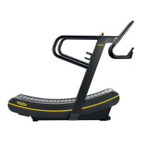
Skillmill:
Technical Service Guide - Rev. 3.5
Page 103email: support@technogym.com