4. Disconnect the angle sensor board connector.
5. Remove the brake frame.
6. Remove the angle sensor, removing the two screws which aach it to the support plate.
After reing the aluminium brake frame, check the tension of the belt. Adjust the tension using the
tensioning device.
7.8 PIN ON WHICH THE ANGLE SENSOR BOARD IS FITTED
7.8.1 DISASSEMBLING THE PIN
Remove the aluminium brake frame as explained in paragraph “7.7.5 Disassembling the aluminium
brake frame”.
It is now possible to remove the pin.
7.8.2 FITTING THE PIN
1. Fit the pin onto the brake frame. The pin lock nut must be tightened with a torque of 2.5 Nm
(1.84 lbf-ft).
2. Calibrate the brake table.
Remember that, from the SW version SKILLMILL CONNECT: High Kit: BA01.49 - wi-: CA01.16;
SKILLMILL CONSOLE: High Kit: BA01.49, a function has been added at SW level to ensure
a check of the correct calibration. For the details, refer to “6.7 Calibrating the brake table”.
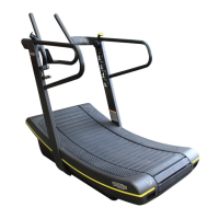
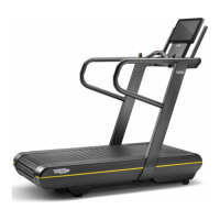
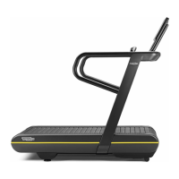
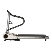
Skillmill
Technical Service Guide - Rev. 3.5
Page 104
email: support@technogym.com