Page 7 - 2
Section 7 – Airframe and Systems description
AIRFRAME
1. INTRODUCTION
This section provides description and operation of the aircraft and its systems.
2. AIRFRAME
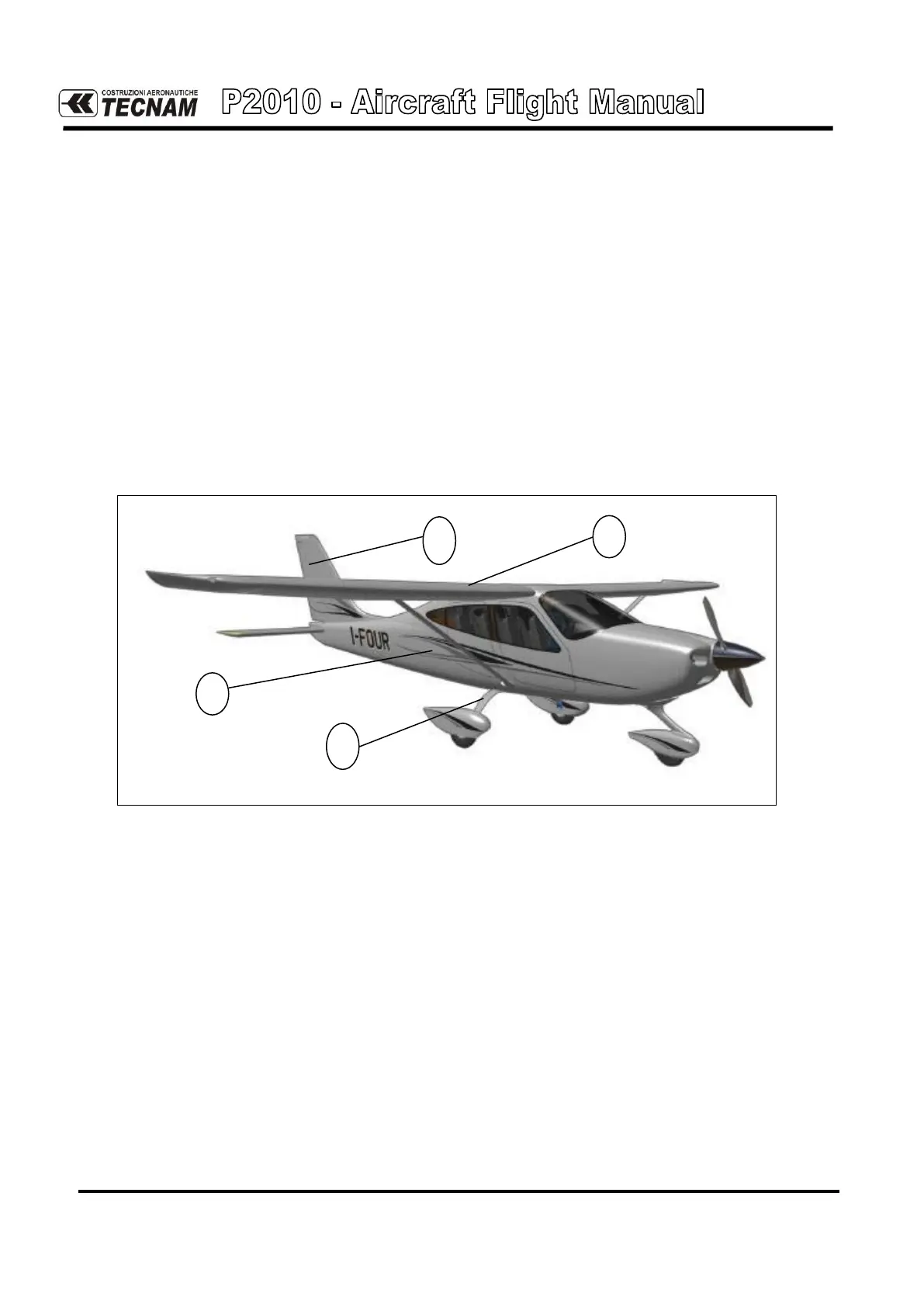
P2010’s airframe can be divided in the following main groups, as highlighted below on fig-
ure 7-1:
1) Wing
2) Fuselage
3) Empennage
4) Landing gear
Fig. 7-1. P2010 AIRFRAME
2.1. WING
Each wing is connected to the fuselage by means of two bolt attachments and a single strut
brace per side. The wings are made up of a central light alloy torsion box; a light alloy lead-
ing edge is attached to the front spar whereas the flap (“slotted”) and the aileron (“frise”) are
attached to a rear spar through two hinges each.
The torsion box consists of a front and rear spar that represent its front and rear vertical
walls; a series of ribs and wrap-around panels complete the structure. Front and rear spars
are integrated with wing-fuselage attachment fittings.
Integral fuel tanks are located in the wing box, behind the main spar, with a capacity of 120
litres each (31,7 gallons).
The ailerons and flaps are made by an aluminium spar attached to a formed sheet metal
leading edge and metal ribs; an aluminium skin surrounds the aileron structure.