Page 7 - 5
Section 7 – Airframe and Systems description
AIRFRAME
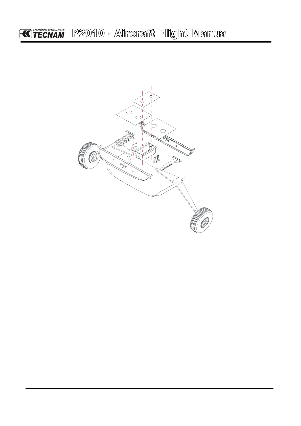
2.4. MAIN LANDING GEAR
The main landing gear consists of two steel leaf-springs positioned crossways to the fuse-
lage.
Fig. 7-4. MAIN LANDING GEAR STRUCTURE
The steel leaf-springs are attached to the fuselage structure on composite beams.
Wheels are cantilevered on gear struts and feature hydraulically actuated disc brakes con-
trolled by toe. Main gear wheels install type 6.00-6 tires inflated at 36 psi (2.5 bar).
P2010 is provided with an independent hydraulically actuated brake system for each main
wheel. A master cylinder is attached to each pilot’s rudder pedal. Hydraulic pressure, ap-
plied via the master cylinders, enters the brake via lines connected to an inlet fitting on the
caliper.
A parking brake valve, mounted in correspondence of the cabin floor and operated by a
knob on the cockpit central pedestal, intercepts the hydraulic lines, once pressurized by toe
brakes, to hold the brake assemblies linings tightened round the main wheels brake discs.
Brakes can be operated from either pilot’s and co-pilot’s pedals: a single vented oil reservoir
feeds the pilot side master cylinders which are connected, via hoses, with the co-pilot’s side
ones.