34
Parameter Name & Function Default Unit
Setting
Range
Control
Mode
Chapter
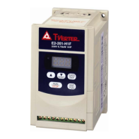
Output time setting for Mechanical Brake Signal
Cn003
Brake Signal Timing Sequence:
Implementation a pin for dynamic brake signal (BI) as a
output signal before to perform this function. Refer to
sequence diagram above.
Note: Signal logic level status: 1 = ON. 0 = OFF.
Refer to Hn501.2 ~ Hn506.2 for setting contact high & Low
logic levels.
0 msec
-2000
│
2000
ALL 5-6-5
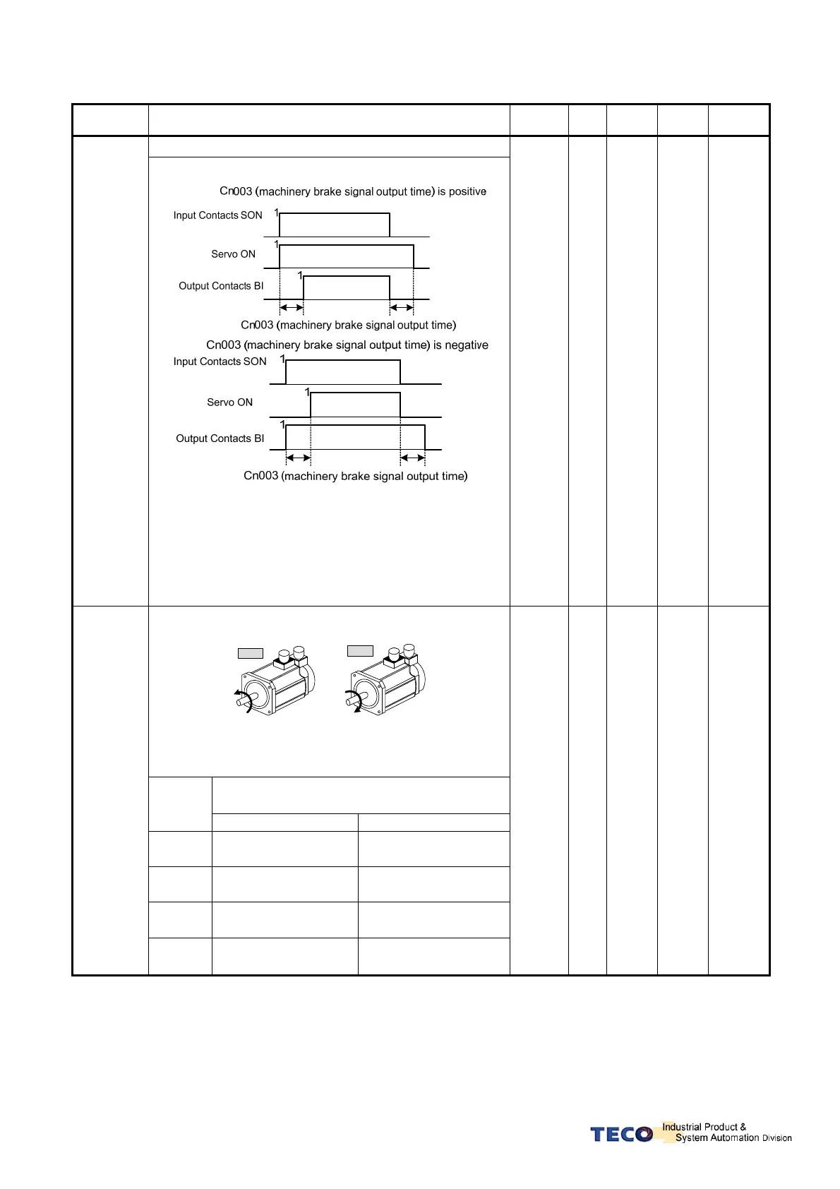
Motor rotate direction.(Inspect from the load side)
CCW
CW
When Torque or Speed Command value is Positive, the
setting of Motor rotation direction are:
Explanation
Setting
Torque Control Speed Control
0
Counter
ClockWise(CCW)
Counter
ClockWise (CCW)
1 ClockWise (CW)
Counter
ClockWise (CCW)
2
Counter
ClockWise (CCW)
ClockWise(CW)
Cn004
3 ClockWise (CW) ClockWise (CW)
0 X
0
│
3
S
T
5-2-4
5-3-7