4-42
Group10- Assistant function group
10- 01 Reverse operation control
Range
【0】:Reverse command is enabled
【1】:Reverse command is disabled
10-01=1, the reverse command is disabled.
10- 03 Carrier Frequency
Range
【1~12】kHz
10-03
Frequency
10-03
Frequency
10-03
Frequency
※Note:1. In applications where there is excessive audible noise from the motor or it is required
to reduce electrical interference (RFI) from the inverter caused by use of long cable then the
carrier frequency can be adjusted. To reduce electromagnetic interference due to long cable etc,
decrease carrier frequency. To reduce motor audible noise, increase carrier frequency.
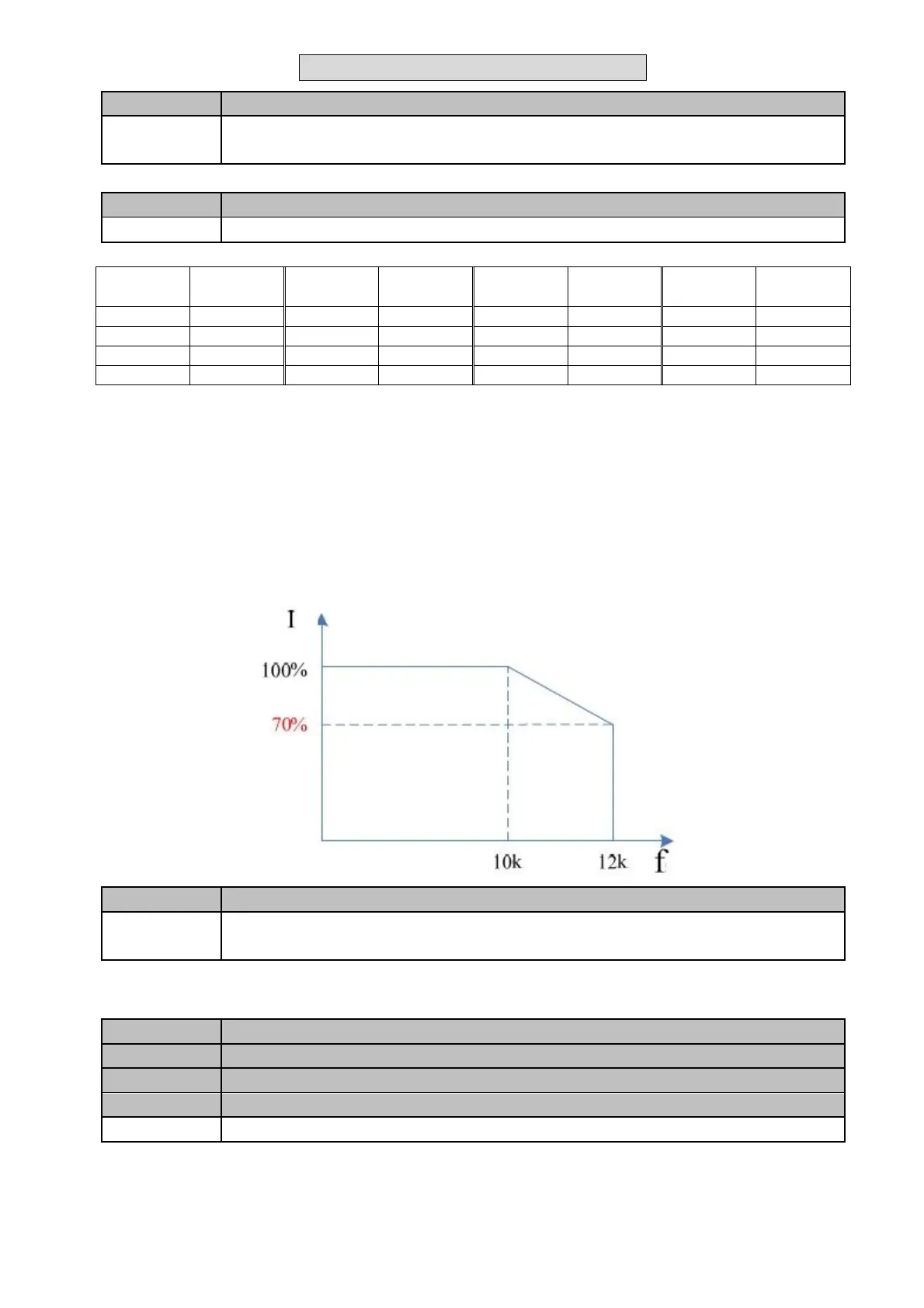
2. The carrier frequency of PWM output must be limited to the rated current of the driver; The
higherthe carrier, the lower the rated current of the drive, is to prevent the drive from heating and
prolong the life of IGBT, so such protection technology is a must. Carrier frequency under 10 KHZ
inverter current rating of 100%, as the carrier with the decrease of higher rated output current and
the rated current and the relationship between the carrier frequency curve of the diagram below
(401/402/405 need not fall 403 according to the following curve down load)
10- 04
Carrier mode selection
Range
【0】:Carrier mode 0
【1】:Carrier mode 1
1.10-04=0: Carrier mode0 is recommended in environments where low noise is required.
Correct ambient temperature and cooling is necessary.
2. 10-04=1: Carrier mode1 is recommended in locations where fan or pumps is required.
10- 07
S-Curve Acc/Dec 1
10- 08
S-Curve Acc/Dec 2
10- 09
S-Curve Acc/Dec 3
10- 10
S-Curve Acc/Dec 4
Range
【0.0 ~ 4.0】Sec
Use S Curve parameters where a smooth acceleration or deceleration action is required, this will
prevent possible damage caused to machines by sudden acceleration/deceleration.
Four parameters can be selected as shown on the diagram below:
 Loading...


