2. HARDWARE SETUP
DC-395 Series User’s Manual
1010
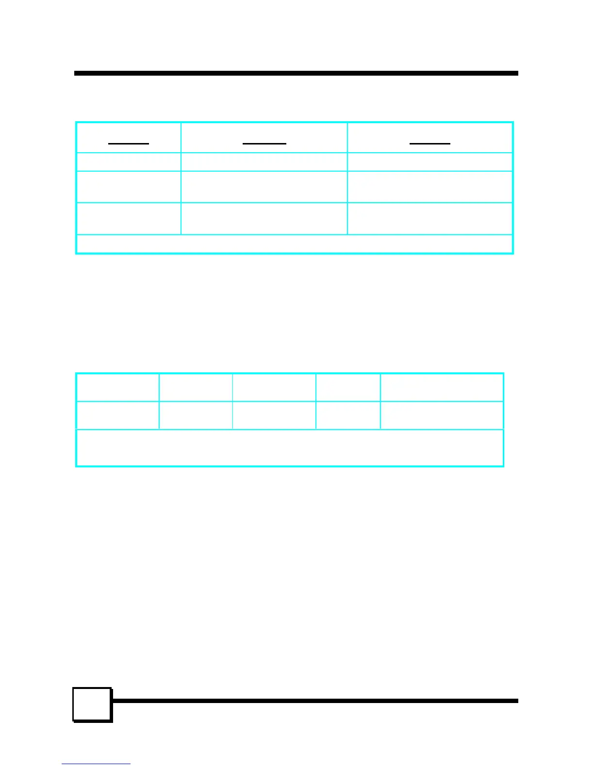
2.5 Cable Connection
Model # External Internal
DC-395U CN1: 50-pin; 8-bit CN2: 50-pin; 8-bit
DC-395UW* CN1: 50-pin; 8-bit CN2: 68-pin; 16-bit (wide)
CN3: 50-pin; 8-bit
DC-395F CN1: 68-pin; 16-bit
CN2: 68-pin; 16-bit (wide)
CN3: 50-pin; 8-bit
* Only two of the three connectors can be used to connect SCSI devices at the same time.
External SCSI connector: This high density D-type SCSI connector is for connecting
external SCSI devices.
Internal SCSI connector: The internal flat cable should connect to the internal SCSI
connector with its colored stripe, normally red, aligned with Pin 1 of the connector.
Maximum length of the SCSI bus is determined by the number of devices and the data
transfer rate. The following table summarizes the maximum allowable cable lengths for the
DC-395 series:
Model # SCSI Type Data Xfer
Rate
Max. # of
Devices
Max. Cable Length
DC-
395U/UW/F
Ultra /Ultra
Wide SCSI
20/40 MB/Sec 4 3meters (9.8 feet)
• If there are internal devices connected, the internal cable length must be included in
the measurement of SCSI bus length.