Theory of Operation—2205 Service
6716-12
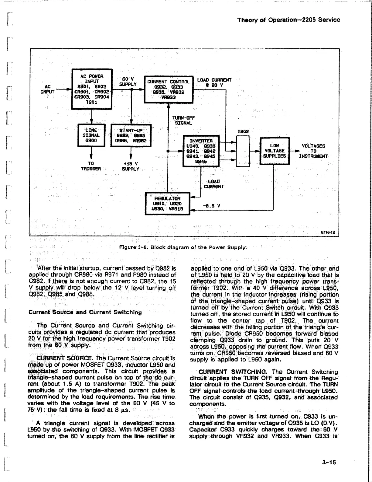
Figure 3-6. Block diagram of the Power Supply.
After the initial Startup, current passed by Q982 is
applied through CR980 via R971 and R980 instead of
C982. If there is not enough current to G982, the 15
V supply will drop below the 12 V level turning off
Q982, Q985 and Q988.
Current Source and Current Switching
The Current Source and Current Switching cir
cuits provides a regulated dc current that produces
20 V for the high frequency power transformer T902
from the 60 V supply.
CURRENT SOURCE. The Current Source circuit is
made up of power MOSFET Q933, inductor L950 and
associated components. This circuit provides a
triangle-shaped current pulse on top of the dc Cur
rent (about 1.5 A) to transformer T902. The peak
amplitude of the triangle-shaped current pulse is
determined by the load requirements. The rise time
varies with the voltage level of the 60 V (45 V to
75 V); the fall time is fixed at 8 jis.
A triangle current signal is developed across
L950 by the switching of Q933. With MOSFET Q933
turned on, the 60 V supply from the line rectifier is
applied to one end of 1950 via Q933. The other end
of L950 is held to 20 V by the capacitive load that is
reflected through the high frequency power trans
former T9Q2. With a 40 V difference across L95Q,
the current in the inductor increases (rising portion
of the triangle-shaped current pulse) until Q933 is
turned off by the Current Switch circuit. With Q933
turned off, the stored current in L950 will continue to
flow to the center tap of T902. The current
decreases with the falling portion of the triangle cur
rent pulse. Diode CR350 becomes forward biased
clamping Q933 drain to ground. This puts 20 V
across L950, opposing the current flow. When Q933
turns on, CR950 becomes reversed biased and 60 V
supply is applied to L950 again.
CURRENT SWITCHING. The Current Switching
circuit applies the TURN OFF signal from the Regu
lator circuit to the Current Source circuit. The TURN
OFF signal controls the load current through L950.
The circuit consist of Q935, Q932, and associated
components.
When the power is first turned on, C933 is un
charged and the emitter voltage of Q935 is LO (0 V).
Capacitor C933 quickly charges toward the 60 V
supply through VR932 and VR933. When C933 is
3-15