Adjustment Procedure—2205 Service
i. Set the Vertical MODE switch to CH 1.
j. Repeat parts b through g using the Channel 1
controls.
f. Check Position Range
a. Set:
VOITS/DIV (both) 10 mV
AC-GND-DC (both) AC
SEC/DIV 0.2 ms
Trigger COUPLING AC
b. Set the calibration generator for 0.1 V.
c. Adjust the CH 1 VOLTS/DIV variable control to
produce a 5.25-division display.
d. Set the CH 1 VOLTS/DIV to 5 mV.
e. Set the calibration generator to produce a
0.2 V signal.
f. CHECK—The bottom and top of the trace may
be positioned above and below the center horizontal
graticule line by rotating the CH 1 POSITION control
fully clockwise and counterclockwise respectively.
g. Move the cable from the CH 1 or X input con
nector to the CH 2 OR Y input connector.
h. Set the Vertical MODE switch to CH 2.
i. Repeat parts b through f using the Channel 2
controls.
j. Disconnect the test equipment from the
instrument.
6. Adjust Attenuator Compensation
a. Set:
VOLTS/DIV (both) 10 mV
AC-GND-DC (both) DC
b. Connect the high-amplitude, square-wave
output from the calibration generator via a 5 0 -fl ter
mination r a miniature probe tip to BNC adapter, and
the 10X probe to the CH 2 OR Y input connector.
c. Set the generator to produce a 1-kHz, 5-
division display and compensate the probe using the
probp compensation adjustment (see the probe
instruction manual).
d. Replace the probe and miniature probe tip to
BNC adapter with a 50-fl coaxial cable and 50-0
termination.
e. Set the generator to produce a 5-division
display.
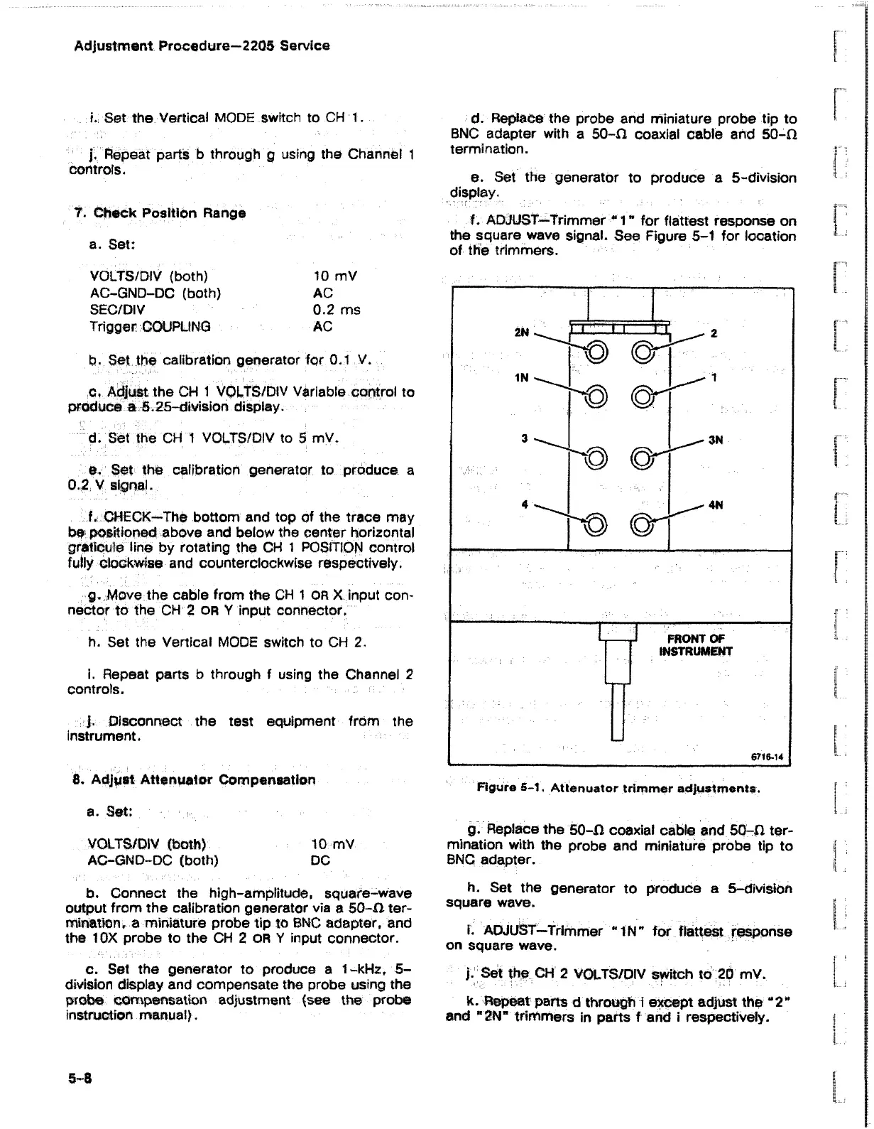
f. ADJUST—Trimmer " 1 ” for flattest response on
the square wave signal. See Figure 5-1 for location
of the trimmers.
g. Replace the 50-fl coaxial cable and 50-fl ter
mination with the probe and miniature probe tip to
BNC adapter.
h. Set the generator to produce a 5-division
square wave.
i. ADJUST—Trimmer "IN ’’ for flattest response
on square wave.
j. Set the CH 2 VOLTS/DIV switch to 20 mV.
k. Repeat parts d through i except adjust the “ 2*
and “ 2N” trimmers in parts f and i respectively.
5-8