Section 6—2205 Service
MAINTENANCE
This section contains information for conducting board removal procedures are included in the Cor-
preventive maintenance, troubleshooting, and cor- rective Maintenance part of this section,
rective maintenance on the instrument. Circuit
STATIC-SENSITIVE COMPONENTS
The following precautions are applicable when
performing any maintenance involving internal
access to the instrument.
a A A A A A A A A m
i CAUTION 1
Static discharge can damage any semi
conductor component in this instrument.
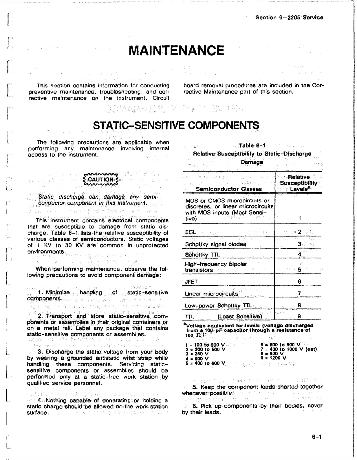
This instrument contains electrical components
that are susceptible to damage from static dis
charge. Table 6-1 lists the relative susceptibility of
various classes of semiconductors. Static voltages
of 1 KV to 30 KV are common in unprotected
environments.
When performing maintenance, observe the fol
lowing precautions to avoid component damage:
1. Minimize handling of static-sensitive
components.
2. Transport and store static-sensitive ; com
ponents or assemblies in their original containers or
on a metal rail. Label any package that contains
static-sensitive components or assemblies.
3. Discharge the static voltage from your body
by wearing a grounded antistatic wrist strap while
handling these components. Servicing static-
sensitive components or assemblies should be
performed only at a static-free work station by
qualified service personnel.
4. Nothing capable of generating or holding a
static charge should be allowed on the work station
surface.
Table 6-1
Relative Susceptibility to Static-Discharge
D am ag e
..........
Semiconductor Classes
Relative-
Susceptibility
Levels®
MOS or CMOS microcircuits or
discretes, or linear microcircuits
with MOS inputs (Most Sensi
tive)
1
ECL .
2
Schottky signal diodes 3
Schottky TTL
4
High-frequency bipolar
transistors
5
JFET 6
Linear microcircuits
7
Low-power Schottky TTL
8
TTL (Least Sensitive)
■ : 9
aVoltage equivalent ter levels (voltage discharged
from a 100-pF capacitor through a resistance of
100 P'J1
1 = 100 to 500 V 6 = 600 to 800 V
2 a 200 to 500 V 7 = 400 to 1000 V (est)
3 * 250 V 8 s 900 V
4 3 500 V 9 * 1200 V
5 3 400 to 600 V
5. Keep the component leads shorted together
whenever possible.
6. Pick up components by their bodies, never
by their leads.
6-1