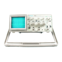
Section 2—2205 Service
OPERATING INFORMATION
PREPARATION FOR USE
This part gives you important safety information procedure to verify that the proper fuse is installed
and tells you how to proceed with initial start-up of or to install a replacement fuse,
the TEKTRONIX 2205 Oscilloscope.
1. Unplug the power cord from the power source
SAFETY (if applicable).
Before connecting the 2205 Oscilloscope to a
power source, read this entire section. Also refer to
the Safety Summary at the front of this manual for
power source, grounding, and other safety con
siderations pertaining to the use of the instrument.
Ensure that you have the training required to safely
connect inputs to the signals you will be measuring.
This instrument may be damaged if oper
ated with the LINE VOLTAGE SELECTOR
(on the rear panel) set for the wrong
applied ac source voltage or If a wrong line
fuse Is installed
LINE VOLTAGE SELECTION
The 2205 operates from either a 115-V or a
230-V nominal ac power fine with any frequency
from 48 Hz to 440 Hz. Before connecting the power
cord to a power source, verify that the LINE
VOLTAGE SELECTOR, located on the rear panel, is
set correctly and that the proper line fuse is
installed. Refer to Table 2-1, Figure 2-1, and the
instrument rear panel.
To convert the 2205 for operation on the other
line-voltage range, use a flat-bladed screwdriver to
move the LINE VOLTAGE SELECTOR to the required
position and install the appropriate fuse (listed on
the rear panel and in Table 7-1). The detachable
power cord may have to be replaced to match the
particular power source.
2. Press in and slightly rotate the fuse-holder cap
counterclockwise to release it.
3. Pull the cap (with the fuse) out of the fuse
holder.
4. Verify that the fuse is the same type listed on
the back of the instrument. The two types of
fuses listed are not directly interchangeable;
they require different types of fuse caps.
5. Reinstall the fuse (or replacement fuse) in the
fuse-holder cap.
6. Replace the fuse holder and cap.
This instrument has a detachable, three-w ire
power cord with a three-contact plug fo r connection
to both the power source and protective ground.
The ground contact on the plug connects through
the power-cord to the external metal parts of the
instrument. The power cord may be secured to the
rear panel by a cord-set-securing clamp as shown
in Figure 2-1. For electrical shock protection, insert
this plug only into a power source outlet that has a
properly grounded protective-ground contact.
Instruments are shipped with the required power
cord as ordered by the customer. Power cord plug
information is presented in Table 2-1, and part num
bers are listed in Table 7-1.
INSTRUMENT COOLING
LINE FUSE
The fuse holder is located on the rear panel and
contains the line (mains) fuse. Use the following
Maintain adequate airflow to prevent instrument
damage from internally generated heat. Before
turning on the power, check that the spaces around
the air-intake holes on the sides of the cabinet are
free of any obstruction to airflow.
2-1

 Loading...