Operating Inform ation—2205 Service
OPERATING CONSIDERATIONS
This part contains basic operating information CONNECTING SIGNALS
said techniques that should be considered before
attempting to make any measurements with the
instrument.
Signal Adapter
GRATICULE
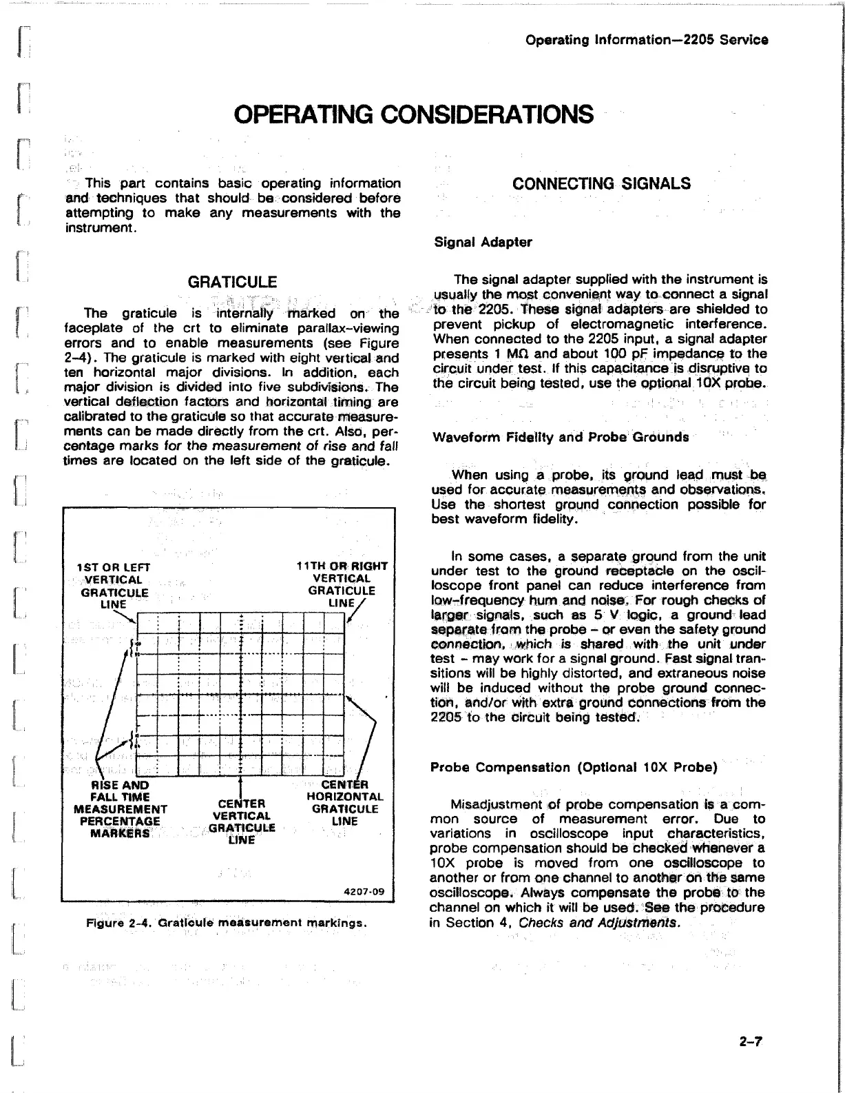
The graticule is internally marked on the
faceplate of the crt to eliminate parallax-viewing
errors and to enable measurements (see Figure
2-4). The graticule is marked with eight vertical and
ten horizontal major divisions. In addition, each
major division is divided into five subdivisions. The
vertical deflection factors and horizontal timing are
calibrated to the graticule so that accurate measure
ments can be made directly from the crt. Also, per
centage marks for the measurement of rise and fall
times are located on the left side of the graticule.
The signal adapter supplied with the instrument is
usually the most convenient way to connect a signal
to the 2205. These signal adapters are shielded to
prevent pickup of electromagnetic interference.
When connected to the 2205 input, a signal adapter
presents 1 MG and about 100 pF impedance to the
circuit under test. If this capacitance is disruptive to
the circuit being tested, use the optional 10X probe.
Waveform Fidelity and Probe Grounds
When using a probe, its ground lead must be
used for accurate measurements and observations.
Use the shortest ground connection possible for
best waveform fidelity.
In some cases, a separate ground from the unit
under test to the ground receptacle on the oscil
loscope front panel can reduce interference from
low-frequency hum and noise, For rough checks of
larger signals, such as 5 V logic, a ground lead
separate from the probe - or even the safety ground
connection, which is shared with the unit under
test - may work for a signal ground. Fast signal tran
sitions will be highly distorted, and extraneous noise
will be induced without the probe ground connec
tion, and/or with extra ground connections from the
2205 to the circuit being tested.
Probe Compensation (Optional 10X Probe)
Misadjustment of probe compensation is a com
mon source of measurement error. Due to
variations in oscilloscope input characteristics,
probe compensation should be checked whenever a
10X probe is moved from one oscilloscope to
another or from one channel to another on the same
oscilloscope. Always compensate the probe to the
channel on which it will be used. See the procedure
in Section 4, Checks and Adjustments.
2-7