Theory of Operation—2205 Service
TV video information and average the TV horizontai-
sync pulses. Setting the trigger-level threshold near
the center of the horizontal-sync-pulse swing es
tablishes the untriggered level. When the TV
vertical-sync-block occurs, the output of the filter
applied to U480S pin 7 rises to a level that will cause
U480B to switch; Precise TV field synchronization is
obtained as a result of this filtering action. The Trig
ger signal output will be the inverse of the filtered
signal appearing at U480B pin 7.
SWEEP GENERATOR AND LOGIC
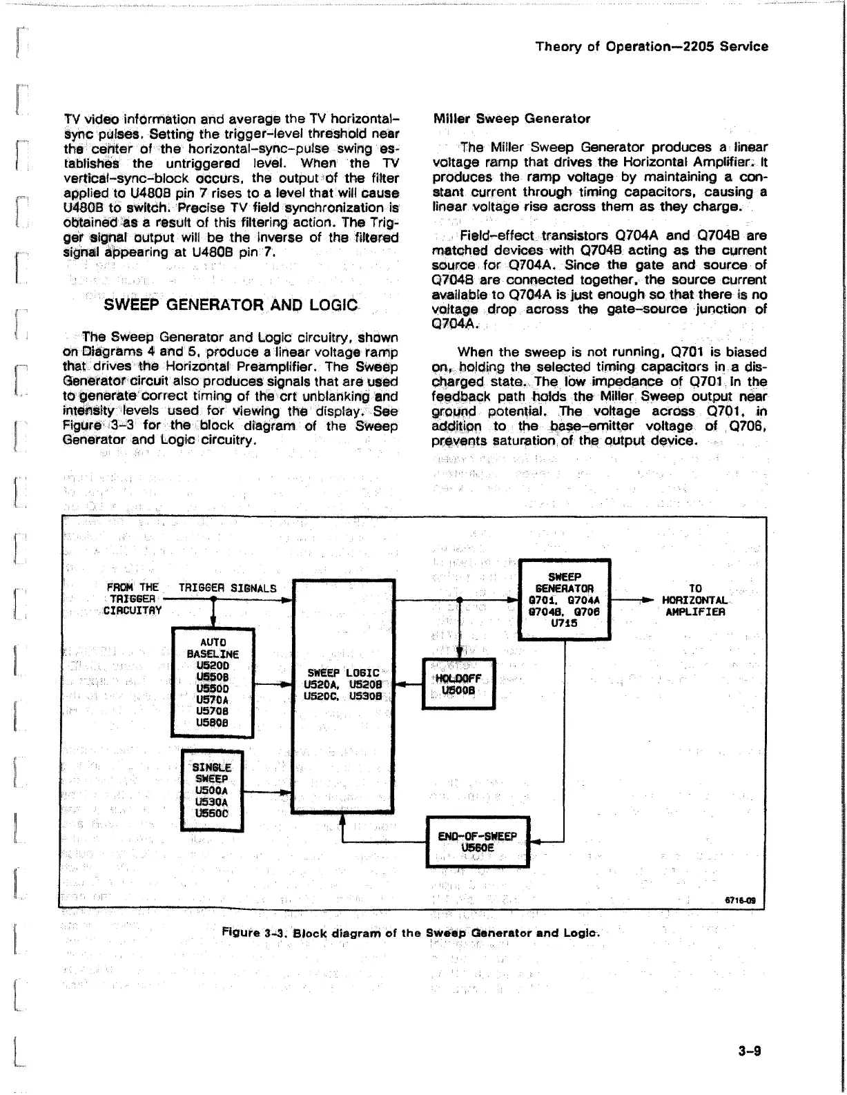
The Sweep Generator and Logic circuitry, shown
on Diagrams 4 and 5, produce a linear voltage ramp
that drives the Horizontal Preamplifier. The Sweep
Generator circuit also produces signals that are used
to generate correct timing of the crt unblanking and
intensity levels used for viewing the display; See
Figure 3-3 for the block diagram of the Sweep
Generator and Logic circuitry.
Miller Sweep Generator
The Miller Sweep Generator produces a linear
voltage ramp that drives the Horizontal Amplifier. It
produces the ramp voltage by maintaining a con
stant current through timing capacitors, causing a
linear voltage rise across them as they charge.
Field-effect transistors Q704A and Q7048 are
matched devices with Q704B acting as the current
source for Q704A. Since the gate and source of
Q7048 are connected together, the source current
available to Q704A is just enough so that there is no
voltage drop across the gate-source junction of
Q704A.
When the sweep is not running, Q701 is biased
on, holding the selected timing capacitors in a dis
charged state. The low impedance of Q701 in the
feedback path holds the Milier Sweep output near
ground potential. The voltage across Q701, in
addition to the base-emitter voltage of Q706,
prevents saturation of the output device.
Figure 3-3. Block diagram of the SWedp Generator and Logie.
3-9