Adjustment Procedure—2205 Service
POWER SUPPLY AND CRT DISPLAY
Equipment Required (See Table 4-1):
Leveled Sine-Wave Generator (item 2)
50-ft Coaxial Cable (Item 6)
Time-Mark Generator (llsrn 3)
50-ft Termination (Item 8)
Digital Voltmeter (Item 5)
Alignment Tool (Item 11)
See
■'AOJUSTMI^
an d a d ju s tm e n t lD c a tio n s 2
at the back of this manual for adjustment locations.
INITIAL CONTROL SETTINGS
INTENSITY Visible display
a. Connect the digital voltmeter low lead to
chassis ground and connect the volts lead to the
-8.6 V, supply (W989).
Vertical
POSITION (both) Midrange
MODE CH 1, NORM
VOLTS/DIV (both) 10 mV
VOLTS/DIV Variable (both) CAL detent
AC-GND-DC (both) GND
Horizontal
POSITION Midrange
MAG XI
SEC/DIV X-Y (fully
ccw)
SEC/DIV Variable CAL detent
Trigger
SLOPE
LEVEL
MODE
SOURCE
Positive (-/“ )
Midrange
P-P AUTO
EXT. EXT
PROCEDURE STEPS
t. Check/Adjust Power Supply DC Levels (R916)
b. CHECK—Voltmeter reading is -8.5 V to
-8.7 V. If the reading is within these limits, skip to
part d.
c. ADJUST—The -8.6 V, Adj potentiometer
(R916) for a voltmeter reading of -8.6 V.
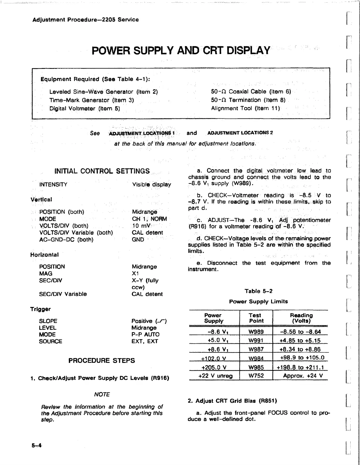
d. CHECK—Voltage levels of the remaining power
supplies listed in Table 5-2 are within the specified
limits.
e. Disconnect the test equipment from the
instrument.
Table 5-2
Power Supply Limits
Power Test
Reading
Supply
Point
(Volts)
-8.6 V,
W989
-8.56 to -8.64
+5.0 V,
W991 +4.85 to +5.15
+8.6 V,
W987
+8.34 to +8.86
+102.0 V
W984
+98.9 to +105.0
+205.0 V W985
+198.8 to +211.1
+22 V unreg
W752 Approx. +24 V
NOTE
Review the information at the beginning of
the Adjustment Procedure before starting this
step.
2. Adjust CRT Grid Bias (R851)
a. Adjust the front-panel FOCUS control to pro
duce a well-defined dot.
5-4