2213 Operators
Table 2
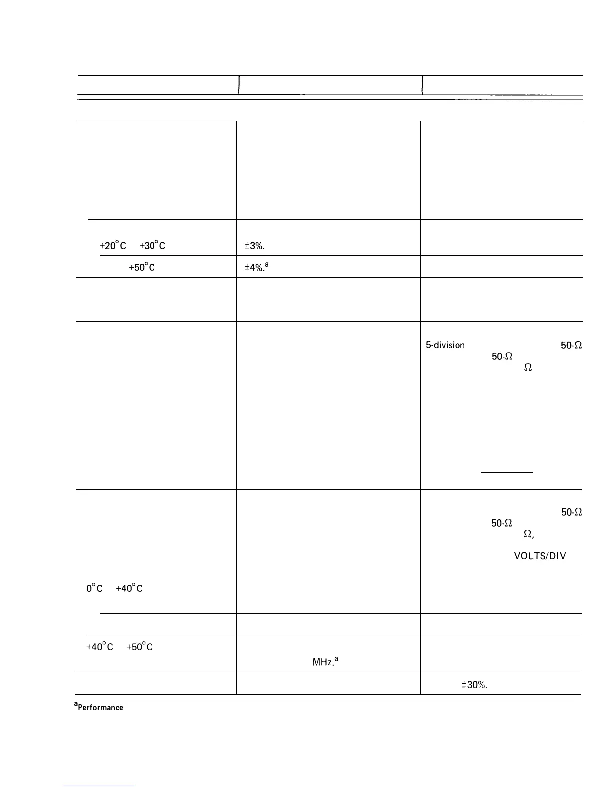
Electrical Characteristics
Characteristics
I
Performance Requirements Supplemental Information
Deflection Factor
Range
Accu racy
+2o”c
to
+3o”c
0°C to
+5o”c
Range of
VOLTS/Dl V
Variable
Control.
Step Response
Rise Time
Bandwidth
o”c
to
+4o”c
20
mV
to 10 V per Division
2
mV
to 10
mV
per Division
+4o”c
to
+5o”c
2
mV
to 10 V per Division
Chop Mode Repetition Rate
VERTICAL DEFLECTION SYSTEM
1X gain adjusted with
VOLTS/DIV
switch set to 20
mV
per division.
2
mV
per division to 10 V per division in
a l-2-5 sequence.
+3%.
+4%.a
Continuously variable between settings.
Increases deflection factor by at least
2.5 to 1.
D
C
to at least 60 MHz.
D
C
to at least 50 MHz.
D
C
to at least 50 MHz.~
10X
gain adjusted with
VOLTS/DIV
switch set to 2
mV
per division.
Measured with a vertically centered
5-divisio n
reference signal from a
50-a
source driving a
50- a
coaxial cable
that is terminated in 50
a
at the input
connector, with the
VOLTS/DlV
Variable control in its CAL detent.
5.8 ns or less.
Rise time is calculated from the
formula:
Rise Time =
0.35
BW (in MHz)
Measured with a vertically centered
6-division reference signal from a
50-a
source driving a
50- a
coaxial cable
that is terminated in 50
s2,
both at the
input connector and at the
P6120
probe input, with the
VOLTS/DIV
Variable control in its CAL detent.
250
kHz
+30%.
aPerformance Requirement not checked in Service Manual.
@
27
 Loading...


