2213 Operators
1. Preset instrument controls and obtain a baseline
trace (refer to “Instrument Familiarization”).
2.
Connect the two 10X probes (supplied with the
instrument) to the CH 1 and CH 2 input connectors.
3. Set both
VOLTS/DIV
switches to 0.1 (10X PROBE)
and set both AC-GND-DC switches to DC.
4. Select CH 1 VERTICAL MODE and insert the tip
of the Channel 1 probe in the PROBE ADJUST output
jack.
5. Using the approximately
1-kHz
PROBE ADJUST
square-wave signal as the input, obtain a display of the
signal (refer to
“Instrument Familiarization”).
6. Set the SEC/DIV switch to display several cycles of
the PROBE ADJUST signal. Use the Channel
1
POSITION
control to vertically center the display.
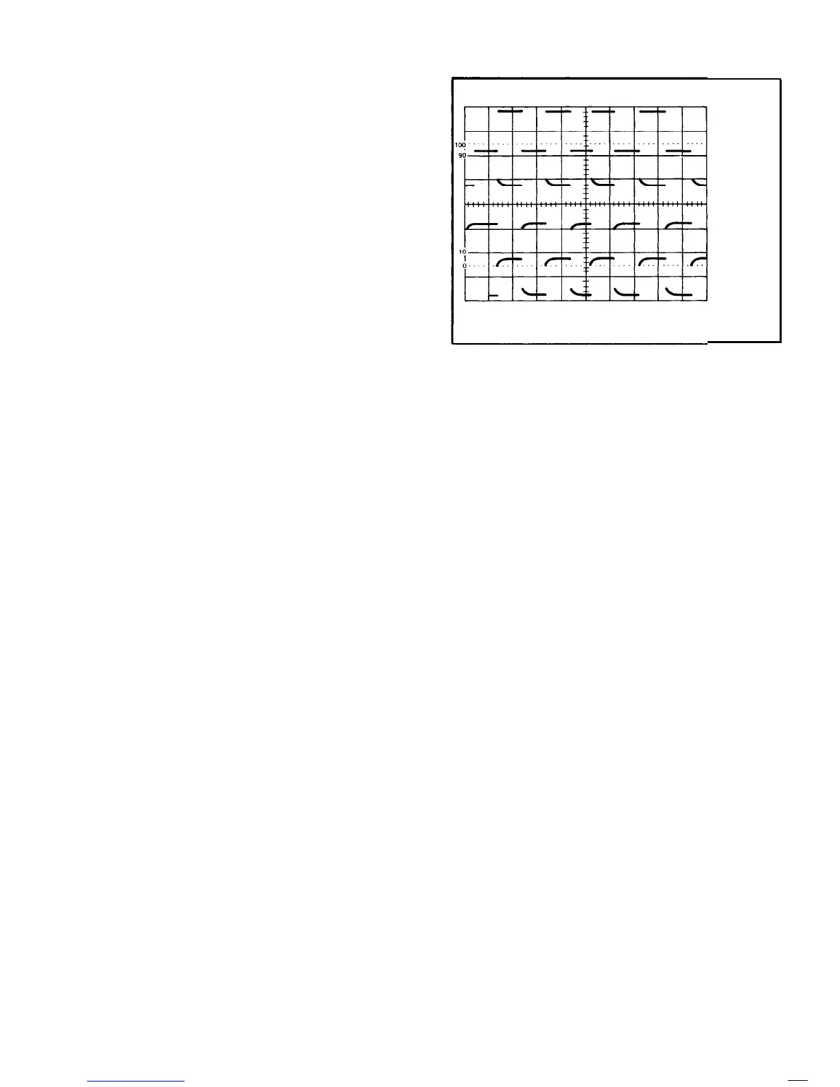
7. Check the waveform presentation for overshoot and
rolloff
(see Figure 10). If necessary, adjust the probe
compensation for flat tops on the waveforms. Refer to the
instructions supplied with the probe for details of com-
pensation adjustment.
BASIC APPLICATIONS
After becoming familiar with all the capabilities of the
2213 Oscilloscope, the operator can then adopt a con-
venient method for making a particular measurement. The
following information describes the recommended pro-
cedures and techniques for making basic measurements
with your instrument.
When a procedure first calls for
presetting instrument controls and obtaining a baseline
trace, refer to the
“Instrument Familiarization” section
and perform steps 1 through 4 under “Baseline Trace.”
NONDELAYED MEASUREMENTS
CORRECT
FLAT
OVER COM-
PENSATED
(OVERSHOOT)
UNDER COM-
PENSATED
(ROLLOFF)
Figure 10. Probe compensation.
8.
Select CH 2 VERTICAL MODE and connect the
Channel 2 probe tip to the PROBE ADJUST output jack.
9. Use the Channel 2 POSITION control to vertically
center the display and repeat step 7 for the Channel 2
probe.
AC Peak-to-Peak Voltage
To perform a peak-to-peak voltage measurement, use the
following procedure:
NOTE
This procedure may also be used to make voltage
measurements between any two points on the
waveform.
1. Preset instrument controls and obtain a baseline
trace.
465/DM-O-5
2.
Apply the ac signal to either vertical-channel input
connector and set the VERTICAL MODE switch to display
the channel used.
3. Set the appropriate
VOLTS/DIV
switch to display
about five divisions of the waveform, ensuring that the
VOLTS/DIV
Variable control is in the CAL detent.
4. Adjust the TRIGGER LEVEL control to obtain a
stable dispaly.
5. Set the SEC/DIV switch to a position that displays
several cycles of the waveform.
6. Vertically position the display so that the negative
peak of the waveform coincides with one of the horizontal
graticule lines (see Figure 11, Point A).
7. Horizontally position the display so that one of the
positive peaks coincides with
the center vertical graticule
line (see Figure 11, Point B).
8. Measure the vertical deflection
from peak to peak
(see
Figure 11, Point A to Point B).
16
REV OCT 1981
 Loading...


