2213 Operators
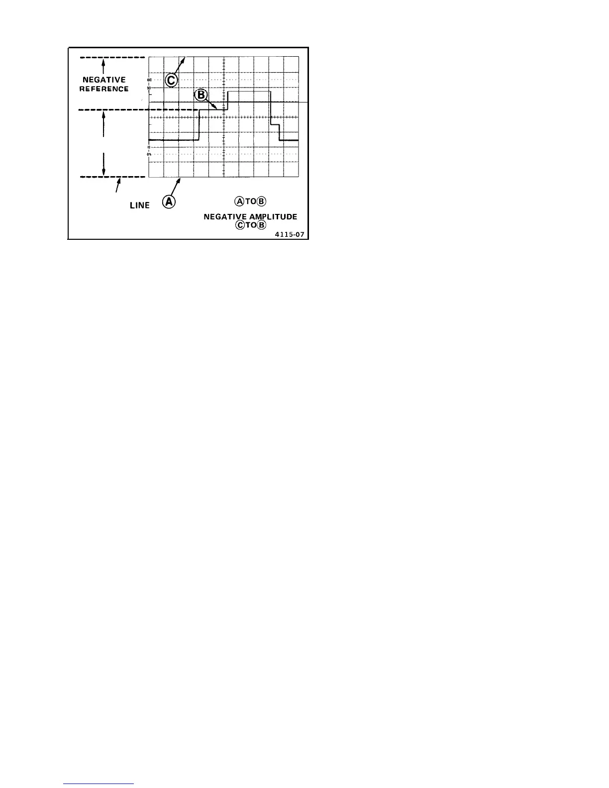
LINE
,
-
VERTICAL
DEFLECTION
POSITIVE
REFERENCE
1
_INE
MEASURE POSITIVE
AMPLITUDE
@TO@
OR
Figure 12. Instantaneous voltage measurement.
12. Calculate the instantaneous voltage, using the fol-
lowing formula:
Instantaneous
vertical
= deflection x
polarity
Voltage
(divisions)
(+ or -)
VOLTS/DlV
probe
X
switch
x attenuation
setting
factor
EXAMPLE:
The measured vertical deflection from the
reference line is 4.6 divisions (see Figure
12),
the wave-
form is above the reference line, the
VOLTS/DIV
switch
is set to 2, and a 10X attenuator probe is being used.
Substituting the given values:
Instantaneous Voltage
=
4.6 div x
(+1)
x 2
V/div
x 10 = 92 V.
Algebraic Addition
With the VERTICAL MODE switch set to BOTH and
ADD, the waveform displayed is the algebraic sum of the
signals applied to the Channel
1
and Channel 2 inputs
(CH
1 +
CH 2). If the Channel 2 INVERT push button is
pressed in,
the waveform displayed is the difference
between the signals applied to the Channel 1 and Channel 2
inputs (CH 1
-
CH 2). The total deflection factor in the
ADD mode is equal to the deflection factor indicated by
either
VOLTS/DIV
switch (when both
VOLTS/DIV
switches are set to the same deflection factor). A common
use for the ADD mode is to provide a dc offset for a signal
riding on top of a high dc level.
The following general precautions should be observed
whenusing the ADD mode.
a.
Do not exceed the input voltage rating of the oscillo-
scope.
b.
Do not apply signals that exceed the equivalent of
about eight times the
VOLTS/DIV
switch settings,
since large voltages may distort the display. For
example, with a
VOLTS/DIV
switch setting of .5, the
voltage applied to that channel should not exceed
approximately 4 volts.
C.
Use Channel 1 and Channel 2 POSITION control
settings which most nearly position the signal on each
channel to midscreen, when viewed in either CH 1 or
CH 2 VERTICAL MODE. This ensures the greatest
dynamic range for ADD mode operation.
d.To attain similar response from each channel, set
both the Channel 1 and Channel 2 AC-GND-DC
switches to the same position.
EXAMPLE: Using the graticule center line as 0 V, the
Channel 1 signal is at a 3-division, positive dc level
(see Figure
13A).
1. Multiply 3 divisions by the
VOLTS/DIV
switch
setting to determine the dc-level value.
2. To the Channel 2 input connector, apply a negative
dc level (or positive level, using the Channel 2 INVERT
switch) whose value was determined in step 1 (see Fig-
ure 13B).
3. Select ADD and BOTH VERTICAL MODE to place
the resultant display within the operating range of the
vertical POSITION controls (see Figure 13C).
Common-Mode Rejection
The ADD mode can also be used to display signals
that contain undesirable frequency components. The
undesirable components can be eliminated through
common-mode rejection. The precautions given under the
preceding “Algebraic Addition” procedure should be
observed.
EXAMPLE: The signal applied to the Channel 1 input
connector contains unwanted ac-input-power-source
frequency components (see Figure 14A). To remove
the undesired components, use the following procedure:
1. Preset instrument controls and obtain a baseline
trace.
18
@