2213
Operators
POSITIVE LEVEL
I
I
I
t
i
100
i
1
9
t
1
NEGATIVEOFFSETI
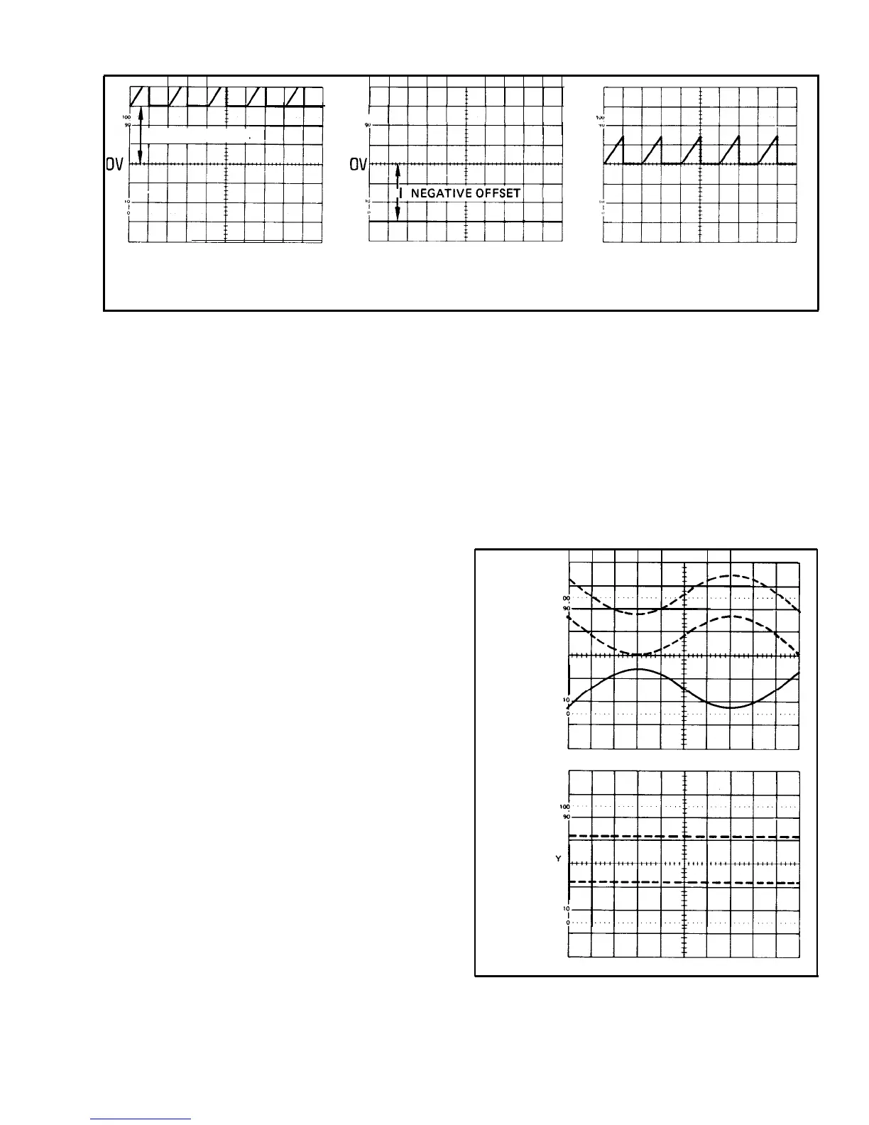
(A) CHANNEL 1 SIGNAL
(B)
CHANNEL 2 DISPLAY
WITH 3 DIVISIONS OF
WITH 3 DIVISIONS OF
(C)
RESULTANT DISPLAY
POSITIVE DC LEVEL.
NEGATIVE OFFSET.
465/DM-0-l9
Figure 13. Algebraic addition.
2. Apply the signal containing the unwanted line-
frequency components to the Channel 1 input.
4.
Set
the
SEC/DIV
switch to display one complete
period of the waveform. Ensure that the
SEC/DIV
Variable
control is in the CAL detent.
3. Apply a line-frequency signal to the Channel 2 input.
4. Select BOTH and ALT VERTICAL MODE and press
in the Channel 2 INVERT push button.
5. Position the display to place the time-measurement
points on the center horizontal graticule line (see Fig-
ure 15).
5. Adjust the Channel 2
VOLTS/DIV
switch and Vari-
able control so that the Channel 2 display is approximately
the same amplitude as the undesired portion of the Chan-
nel 1 display (see Figure 14A).
6. Select ADD VERTICAL MODE and slightly readjust
the Channel 2
VOLTS/DIV
Variable control for maximum
cancellation of the undesired signal component (see
Figure 14B).
Time Duration
To measure time between two points on a waveform,
use the following procedure:
1. Preset instrument controls and obtain a baseline
trace.
2. Apply the signal to either vertical-channel input
connector and set the VERTICAL MODE switch to display
the channel used.
3. Adjust the TRIGGER LEVEL control to obtain a
stable display.
CH 1 SIGNAL
WITH UNWANTED
LINE FREQUENCY
COMPONENT
CH 2 SIGNAL
FROM LINE
FREQUENCY
SOURCE
(INVERTED)
SIGNAL WITH
LINE FREQUENC
COMPONENT
CANCELED
OUT
(A)
CH 1 AND CH 2 SIGNALS.
(B)
RESULTANT SIGNAL.
1738-19
Figure 14. Common-mode rejection.
@
19
 Loading...


