With either
INTENS
or
DLY’D HORIZONTAL MODE
selected, the
DELAY TIME
Range Selector switch and the
MULTIPLIER control provide continuously variable
positioning of the start of the delayed sweep. The DELAY
TIME Range Selector switch allows the start of the inten-
sified zone to be placed near the point of interest, while
the MULTIPLIER control provides fine adjustment of the
intensified zone.
When viewing aperiodic signals (such as complex digital
waveforms) with DLY’D HORIZONTAL MODE selected,
the start of the sweep may not be at the same point as the
start of the intensified zone. It may be necessary to connect
a reference signal (of the system under test) to the EXT
INPUT connector to ensure correct display of the selected
portion of the waveform.
Using delayed-sweep magnification may produce a
display with some slight horizontal movement (pulse jitter).
Pulse jitter includes not only the inherent uncertainty of
triggering the delayed sweep at exactly the same trigger
point each time, but also jitter that may be present in the
input signal. If pulse jitter needs to be measured, use the
“Pulse Jitter Time Measurement” procedure which follows
the discussion of “Magnified Sweep.”
Magnified Sweep
The following procedure explains how to operate the
delayed-sweep feature and to determine the resulting
apparent magnification factor.
1. Preset instrument controls and obtain a baseline trace.
2. Apply the signal to either vertical channel input
connector and set the VERTICAL MODE switch to display
the channel used.
3. Set the appropriate
VOLTS/DIV
switch to produce
a display of approximately 5 divisions in amplitude and
center the display.
4. Set the
SEC/DIV
switch to a sweep speed which
displays at least one complete waveform cycle.
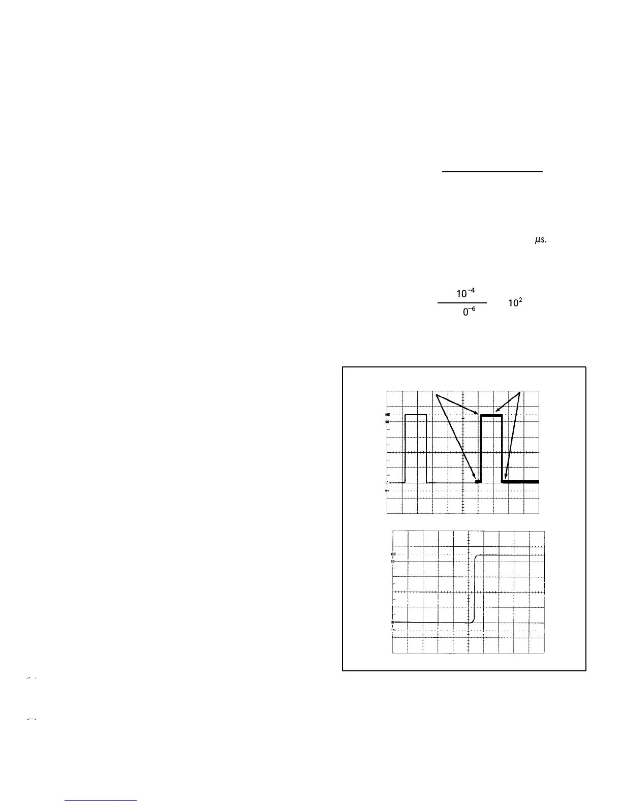
5.
Select
INTENS
HORIZONTAL MODE and set the
DELAY TIME Range Selector switch for the appropriate
delayed time. Adjust the MULTIPLIER control to position
the start of the intensified zone to the portion of the
display to be magnified (see Figure 20A).
2213 Operators
6.
Select the DLY’D HORIZONTAL MODE and
increase the sweep speed to magnify the intensified portion
of the sweep (see Figure 20B).
7. The apparent sweep magnification can be calculated
from the following formula:
Apparent
Delayed Sweep =
initial
SEC/DIV
setting
Magnification
second
SEC/DIV
setting
EXAMPLE: Determine the apparent magnification of a
display with an initial
SEC/DIV
switch setting of 0.1 ms
and the second
SEC/DIV
switch setting of 1
ps.
Substituting the given values:
Apparent
1 x
1o-4 s
=
=
lo2
= 100
Magnification
1 x 1
o-+
s
POINT OF INTEREST INTENSIFIED
TO BE MAGNIFIED
ZONE
(A) INTENSIFIED TRACE
(B) MAGNIFIED TRACE
3397-2
1
Figure 20. Delayed-sweep magnification.
@
25