2213 Operators
POSITION TO
CENTERLINE
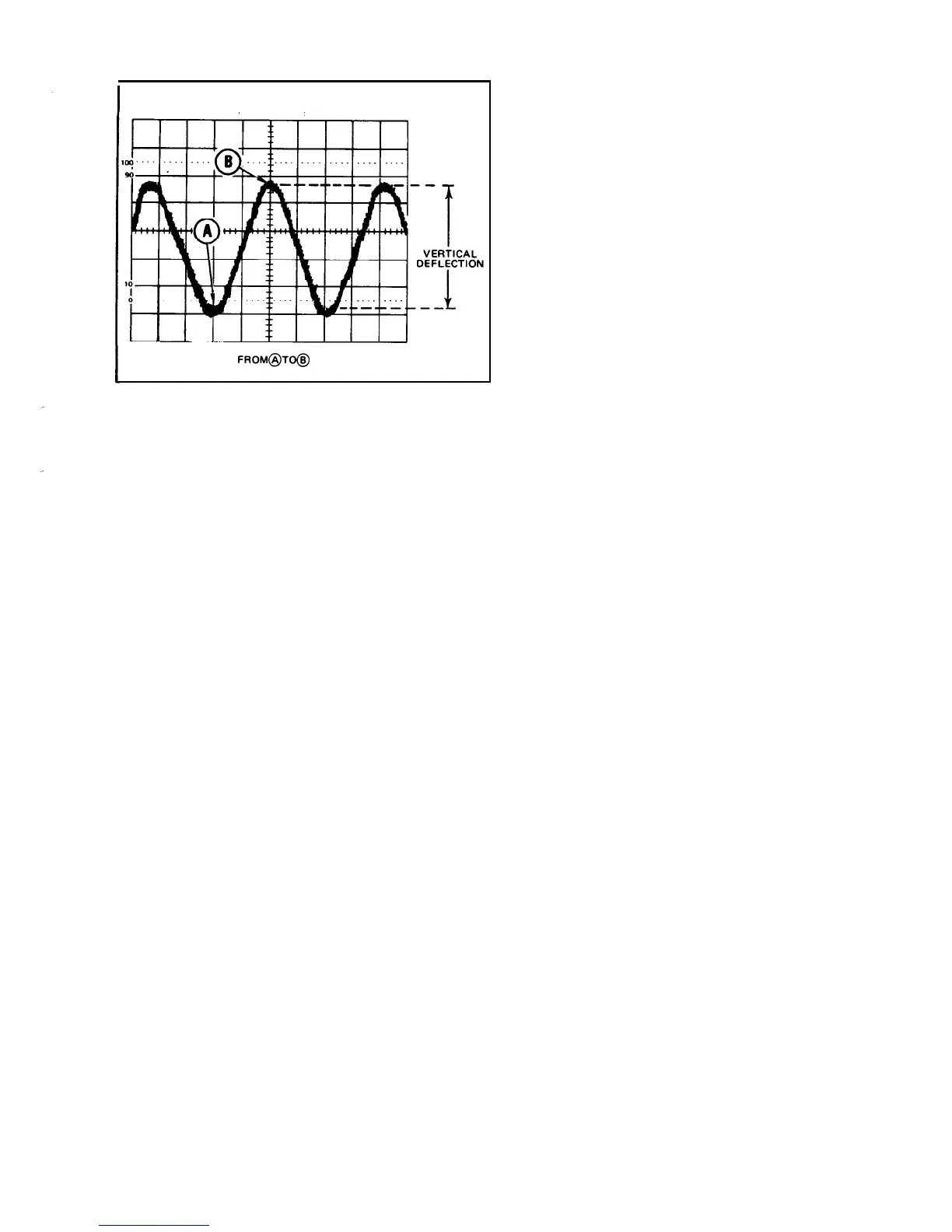
MEASURE AMPLITUDE
FROM@TO@
(1738-l 612038-l 5
Figure 11. Peak-to-peak waveform voltage.
NOTE
If the amplitude measurement is critical or if the
trace is thick (as a result of hum or noise on the
signal), a more accurate value can be obtained by
measuring from the top of a peak to the top of a
valley. This will eliminate trace thickness from the
measurement.
--
9.
Calculate the
peak-to-peak voltage, using the
fol-
lowing formula:
--
vertical
VOLTS/DIV
probe
Volts (p-p) = deflection x
switch
x attenuation
(divisions)
setting
factor
EXAMPLE:
The measured peak-to-peak vertical deflec-
tion is 4.6 divisions (see Figure 11) with a
VOLTS/DIV
switch setting of 0.5, using a 10X probe.
2. Apply the signal to either vertical-channel input
connector and set the VERTICAL MODE switch to display
the channel used.
3. Verify that the
VOLTS/DlV
Variable control is in
the CAL detent and set the AC-GND-DC switch to GND.
4. Vertically position the baseline trace to the center
horizontal graticule line.
5. Set the AC-GND-DC switch to DC. If the waveform
moves above the centerline of the crt, the voltage is positive.
If the waveform moves below the centerline of the crt,
the voltage is negative.
NOTE
If using Channel 2, ensure that the Channel
2
INVERT switch is in its noninverting mode (push
button out).
6.
Set the AC-GND-DC switch to GND and position the
baseline trace to a convenient reference line, using the
Vertical POSITION control. For example, if the voltage to
be measured is positive, position the baseline trace to the
bottom graticu le I ine.
If a negative voltage is to be
measured, position the baseline trace to the top graticule
line. Do not move the Vertical POSITION control after
this reference line has been established. The ground refer-
ence line can be checked at any later time by switching the
AC-GND-DC switch to GND.
7. Set the AC-GND-DC switch to DC.
8. If the voltage-level measurement is to be made with
respect to a voltage level other than ground, apply the
reference voltage to the unused vertical-channel input
connector. Then position its trace to the reference line.
Substituting the given values:
Volts (p-p)
=
4.6 div x 0.5
V/div
x 10 = 23 V.
9. Adjust the TRIGGER LEVEL control to obtain a
stable display.
Instantaneous DC Voltage
To measure the dc level at a given point on a waveform,
use the following procedure:
__ __
1. Preset instrument controls and obtain a baseline
trace.
10. Set the
SEC/DIV
switch to a position that displays
several cycles of the signal.
11.
Measure the divisions of vertical deflection between
the reference line and the desired point on the waveform
at which the dc level is to be determined (see Figure 12).
@
17
 Loading...


