2213 Operators
Table 2
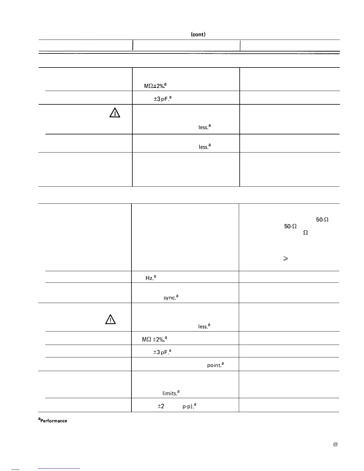
(cant)
Characteristics
I
Performance Requirements
Supplemental Information
VERTICAL DEFLECTION SYSTEM
(cont)
Input Characteristics
Resistance
1
Ma
+2%
a
-
.
30 pF
It3
PF.~
Capacitance
Maximum Safe Input Voltage
1
A
.
DC Coupled
400 V (dc + peak ac) or
800 V p-p ac to 1
kHz
or
less.a
AC Coupled
400 V (dc + peak ac) or
800 V p-p ac to 1
kHz
or
less.a
At least 10 to 1 at 10 MHz.
Checked at 20
mV
per division for
common-mode signals of
8
divisions or
less, with
VOLTS/DIV
Variable control
adjusted for best CMRR at 50
kHz.
Common-Mode Rejection Ratio
(CMRR)
TRIGGER SYSTEM
Trigger Sensitivity
AUTO and NORM
0.4
division internal or 50
mV
external
to 2 MHz, increasing to 1.5 divisions
internal or 250 mV external at 60 MHz.
External trigger signal from a
50-Q
source driving a
50-Q
coaxial cable
that is terminated in 50
a
at the input
connector.
Will trigger on tv line sync components
in NORM only:
>
0.4 division internal
or 50
mV
p-p external.
20
Hz.~
AUTO Lowest Usable Frequency
TV FIELD
2.0 divisions of composite video or
composite
sync.a
External Input
Maximum Input Voltage
!
A
400
V (dc + peak ac) or
800 V p-p ac at 1
kHz
or
less.a
Input Resistance 1
MQ_+2%a
.
30
pF
+3
PF.~
Input Capacitance
AC Coupled
10 Hz or less at lower -3 dB
point.a
LEVEL Control Range
(with NORM TRIGGER MODE)
INT On screen
limits.a
EXT and DC
At least
+2 V (4 V
p-~).~
aPerformance Requirement not checked in Service Manual.
28