2213 Operators
3. Wait several seconds for the input coupling capacitor
to discharge.
6. Set the AC-GND-DC switch to AC. The display will
remain on the screen, and the ac component of the signal
can be measured in the normal manner.
4. Connect the probe tip to the signal source.
INSTRUMENT COOLING
5. Wait several seconds for the input coupling capacitor
to charge.
To maintain adequate instrument cooling, the ventila-
tion holes on both sides and rear panel of the equipment
cabinet must remain free of obstructions.
INSTRUMENT FAMILIARIZATION
INTRODUCTION
The procedures in this section are designed to assist you
in quickly becoming familiar with the 2213. They provide
information which demonstrates the use of all the controls,
connectors, and indicators and will enable you to effi-
ciently operate the instrument.
Before proceeding with these instructions, verify that
the POWER switch is OFF (push button out), then plug
the power cord into the ac-power-input-source outlet.
If during the performance of these procedures an im-
proper indication or instrument malfunction is noted, first
verify correct operation of associated equipment. Should
the malfunction persist, refer the instrument to qualified
service personnel for repair or adjustment.
The equipment listed in Table 1, or equivalent equip-
ment,
is
required to complete these familiarization
procedures.
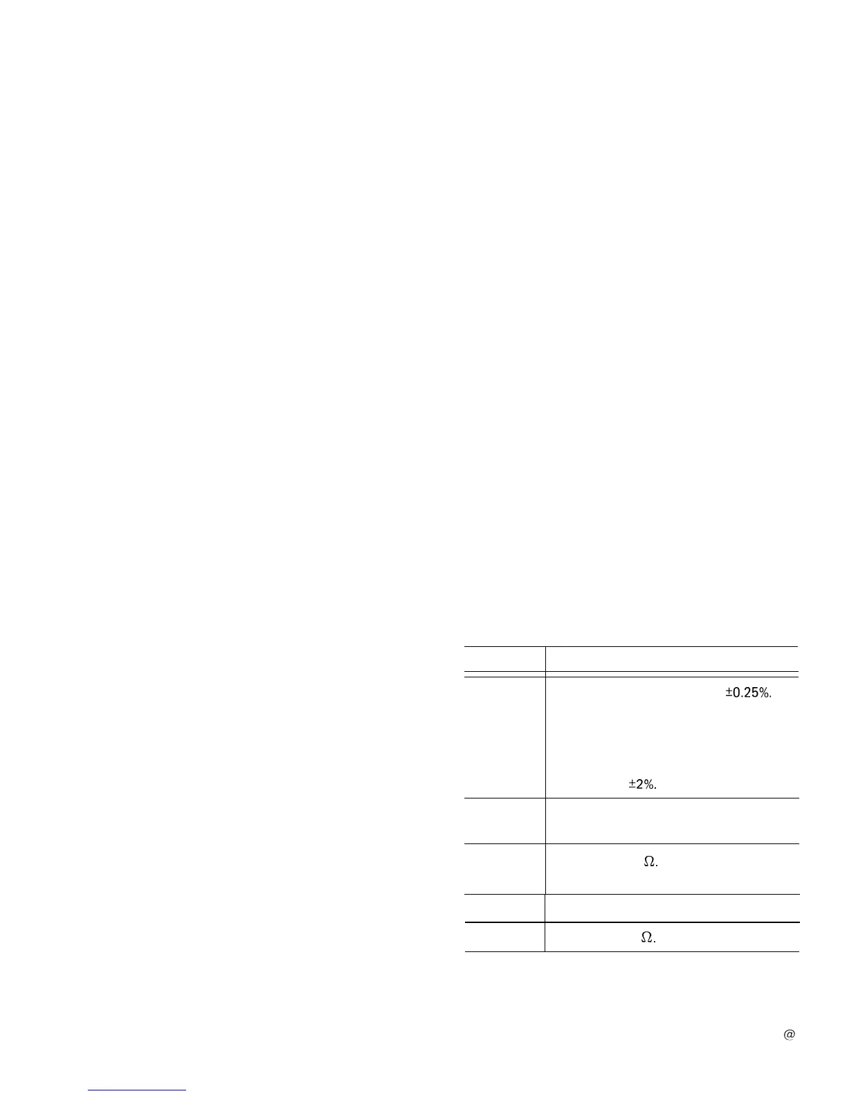
Table 1
Equipment Required for Instrument
Familiarization Procedure
Description
Minimum Specification
Calibration
Generator
Standard-ampl
itude accuracy:
50.25%.
Signal amplitude: 2
mV
to 50 V.
Output signal: 1 -kHz square wave.
Fast-rise repetition rate: 1 to
100
kHz.
Rise time: 1 ns or less.
Signal amplitude: 100
mV
to 1 V.
Aberrations:
+2%.
Dual-Input
Coupler
Connectors: bnc-female-to-dual-bnc-male.
Cable
(2 required)
Impedance: 50
s2.
Length: 42 in.
Connectors: bnc.
Adapter
Connectors: bnc-female-to-bnc female.
Termination
Impedance: 50
a.
Connectors: bnc.
10