2213 Operators
1738-20
I
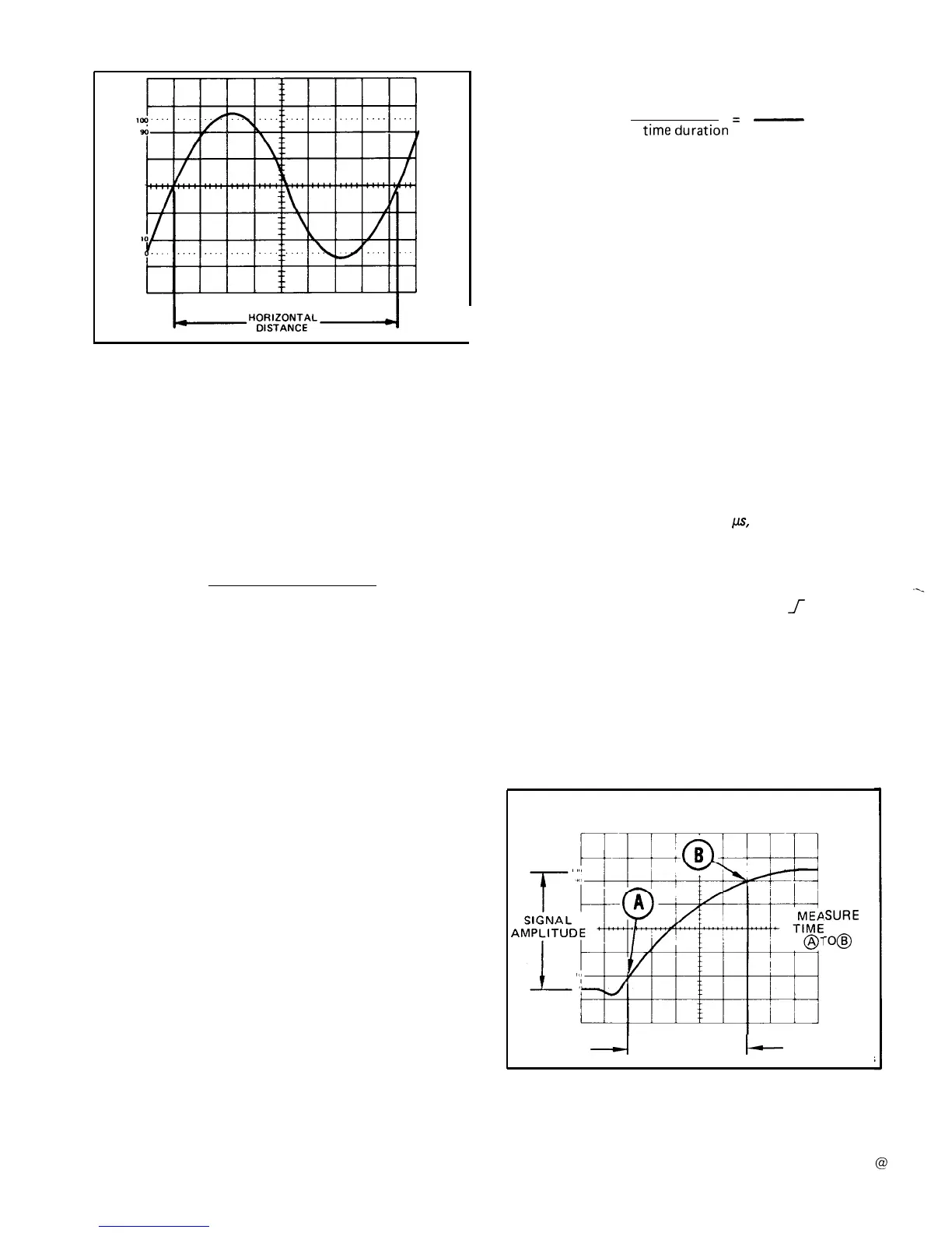
Figure 15. Time duration.
6.
Measure the horizontal distance between the
time-
measurement points.
7. Calculate time duration, using the following formula:
horizontal
SEC/DIV
distance x switch
Time
(divisions)
setting
Duration
=
magnification factor
EXAMPLE:
The distance between the time-measurement
points
is 8.3 divisions (see Figure
15),
and the
SEC/DIV
switch is set to 2 ins. The X10 Magnifier switch is
pushed in (1 X magnification).
Substituting the
given values:
Time Duration
= 8.3 div x 2 ms/div = 16.6 ms
Frequency
The frequency of a recurrent signal can be determined
from its time-duration measurement as follows:
1. Measure the time duration of one waveform cycle
using the preceding “Time Duration” measurement
pro-
cedu
re.
2. Calculate the reciprocal of the time-duration value
to determine the frequency of the waveform.
Calculating the reciprocal of time duration:
1
Frequency
=
time
duration
=
1
-
= 60 Hz
16.6 ms
Rise Time
Rise-time measurements use the same methods as time
duration, except that the measurements are made between
the 10% and 90% points on the leading edge of the wave-
form (see Figure 16). Fall time is measured between the
90% and 10% points on the trailing edge of the waveform.
1. Preset instrument controls and obtain a baseline
trace.
2. Apply an exact 5-division signal to either
vertical-
channel input connector and set the VERTICAL
MODE
switch to display the channel
used. Ensure that the
VOLTS/DIV
Variable control
is in the CAL detent.
NOTE
For rise time greater than 0.2
þÿ¼s, th
Variable control may be used to
S-division display.
the VOL TS/D/ V
obtain an exact
3.
Set the
TRIGGER SLOPE switch to
f
(plus).
Use
a
sweep-speed setting that displays several complete cycles
or events (if possible).
4.
Adjust vertical positioning so that the zero reference
of the waveform touches the 0% graticule line and the top
of the waveform touches the 100% graticule line (see
Figure 16).
#SURE
FROM
-0@
---I
HORIZONTAL
DISTANCE
I--
465/DM-0-13
EXAMPLE:
The signal in Figure 15 has a time duration
of 16.6
ms.
Figure 16. Rise time.
20
 Loading...


