2213 Operators
DC-All
components of the signal are coupled to
the trigger circuitry. This position
is
useful
for
displaying low-frequency or low-repetition-rate
signals.
DC+lO-External
trigger signals are attenuated by
a factor of 10.
0
25
SOURCE Switch-Determines the source of the
trigger signal that is coupled to the input of the
trigger circuit.
INT-Permits triggering on signals that are applied
to the CH 1 OR X and CH 2 OR Y input con-
nectors.
The source of the internal signal is
selected by the INT switch.
LINE-Provides a triggering signal from a sample
of the ac-power-source waveform. This trigger
source is useful when channel-input signals are
time related (multiple or submultiple) to the
frequency on the power-source-input voltage.
EXT-Permits triggering on signals applied to the
EXT INPUT connector.
3397-07
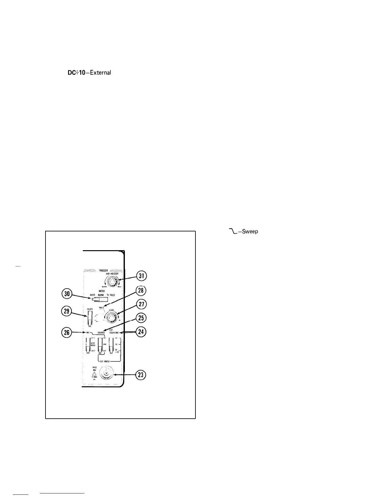
Figure 6. Trigger controls, connector, and indicator.
0
26
0
27
0
28
0
29
0
30
0
31
INT Switch-Selects the source of the triggering
signal when the
SOURCE switch is set to INT.
CH I-The signal applied to the CH 1 OR X input
connector is the
source of the trigger signal.
VERT MODE-The internal trigger source is
determined by the signals selected for display by
the VERTICAL MODE switches.
CH
2-The signal applied to the CH 2 OR Y input
connector is the source of the trigger signal.
LEVEL Control-Selects the amplitude point on the
trigger signal at
which
the sweep is triggered.
TRIG’D Indicator-The light-emitting diode (LED)
illuminates to indicate that the sweep is triggered.
SLOPE Switch-Selects the slope of the signal that
triggers the sweep (also refer to TV Signal Displays at
the end of “Instrument Familiarization”).
I-Sweep is
triggered on the positive-going
portion of the trigger signal.
I-Sweep
is triggered on the negative-going
portion of the trigger signal.
MODE Switch-Determines the trigger mode for the
sweep.
AUTO-Permits triggering on waveforms having
repetition rates of at least 20 Hz. Sweep free-runs
in the absence of an adquate trigger signal or when
the repetition rate is below 20 Hz. The range of
the TRIGGER LEVEL control will compensate
for the amplitude variations of the trigger signals.
NORM-Sweep is initiated when an adequate
trigger signal is applied.
In the absence of a trigger
signal, no baseline trace will be present. Triggering
on television lines is accomplished in this mode.
TV FIELD-Permits triggering on television field-
rate signals (refer to
TV
Signal Displays at the end
of “Instrument Familiarization”.
VAR HOLDOFF
Control-Provides continuous con-
trol of
holdoff
time between sweeps. Increases
the
holdoff
time by at least a factor of four. This
control improves the ability to trigger on aperiodic
signals (such as complex digital waveforms).
REV NOV 1981