3-80
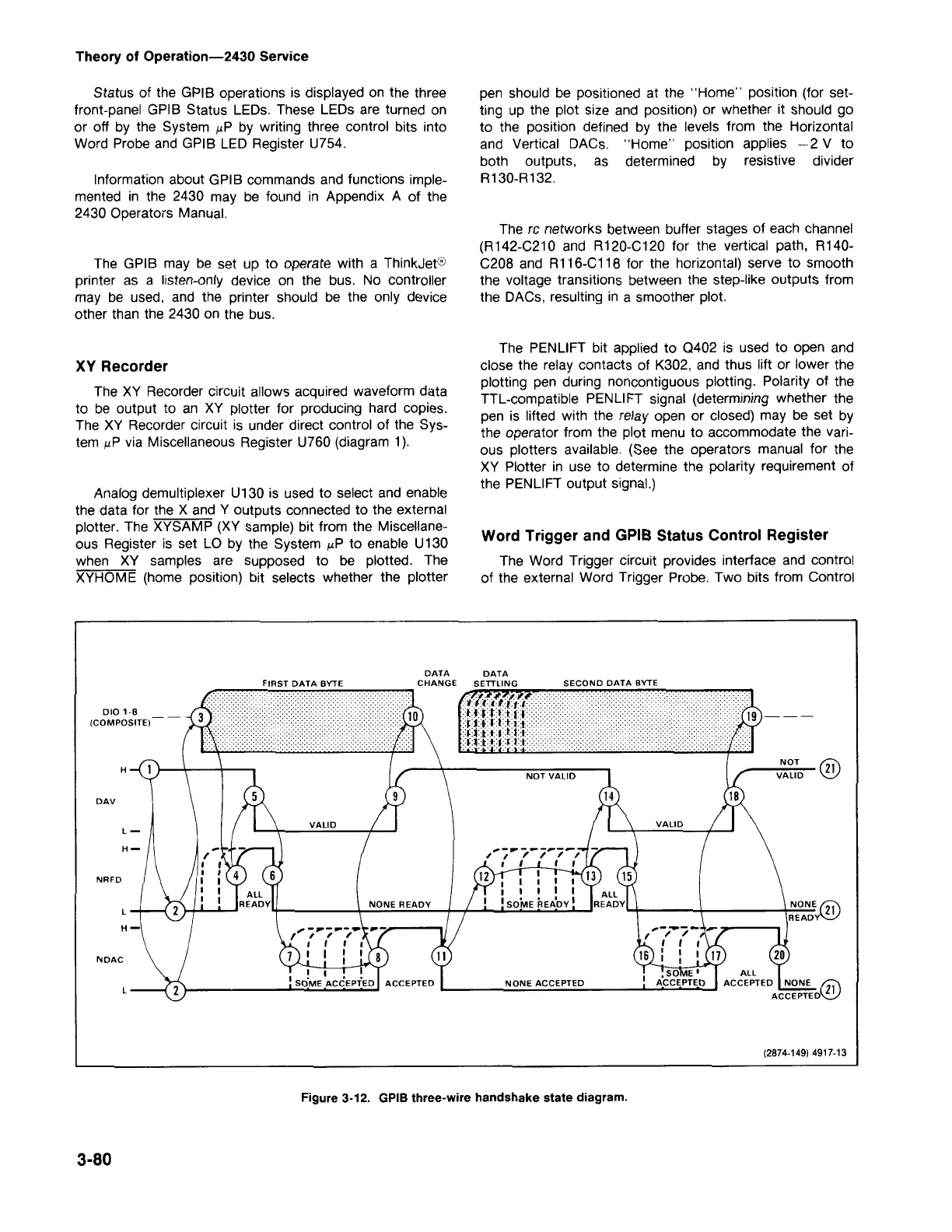
Figure 3-12. GPIBthree-wire handshake state diagram.
(2874-149) 4917-13
NONE ACCEPTED
NDAC
H
NRFD
DAV
NOT VALID
DATA
H
010'·8
(COMPOSITE)
Word Trigger and GPIBStatus Control Register
The Word Trigger circuit provides interface and control
of the external Word Trigger Probe. Two bits from Control
The PENLIFT bit applied to Q402 is used to open and
close the relay contacts of K302, and thus lift or lower the
plotting pen during noncontiguous plotting. Polarity of the
TTL-compatible PENLIFT signal (determining whether the
pen is lifted with the relay open or closed) may be set by
the operator from the plot menu to accommodate the vari-
ous plotters available. (See the operators manual for the
XY Plotter in use to determine the polarity requirement of
the PENLIFT output signal.)
The rc networks between buffer stages of each channel
(R142-C210 and R120-C120 for the vertical path, A140-
C208 and R116-C118 for the horizontal) serve to smooth
the voltage transrtions between the step-like outputs from
the DACs, resulting in a smoother plot.
pen should be positioned at the "Home" position (for set-
ting up the plot size and position) or whether it should go
to the position defined by the levels from the Horizontal
and Vertical DACs. "Home" position applies -2 V to
both outputs, as determined by resistive divider
A130-A132.
Analog demultiplexer U130 is used to select and enable
the data for the X and Y outputs connected to the external
plotter. The XYSAMP (XY sample) bit from the Miscellane-
ous Register is set LO by the System /-LPto enable U130
when XY samples are supposed to be plotted. The
XYHOME (home position) bit selects whether the plotter
XV Recorder
The XY Recorder circuit allows acquired waveform data
to be output to an XY plotter for producing hard copies.
The XY Recorder circuit is under direct control of the Sys-
tem /-LPvia Miscellaneous Register U760 (diagram 1).
The GPIB may be set up to operate with a ThinkJet®
printer as a listen-only device on the bus. No controller
may be used, and the printer should be the only device
other than the 2430 on the bus.
Information about GPIB commands and functions imple-
mented in the 2430 may be found in Appendix A of the
2430 Operators Manual.
Status of the GPIB operations is displayed on the three
front-panel GPIB Status LEDs. These LEDs are turned on
or off by the System /-LPby writing three control bits into
Word Probe and GPIB LED Register U754.
Theory of Operation-2430 Service