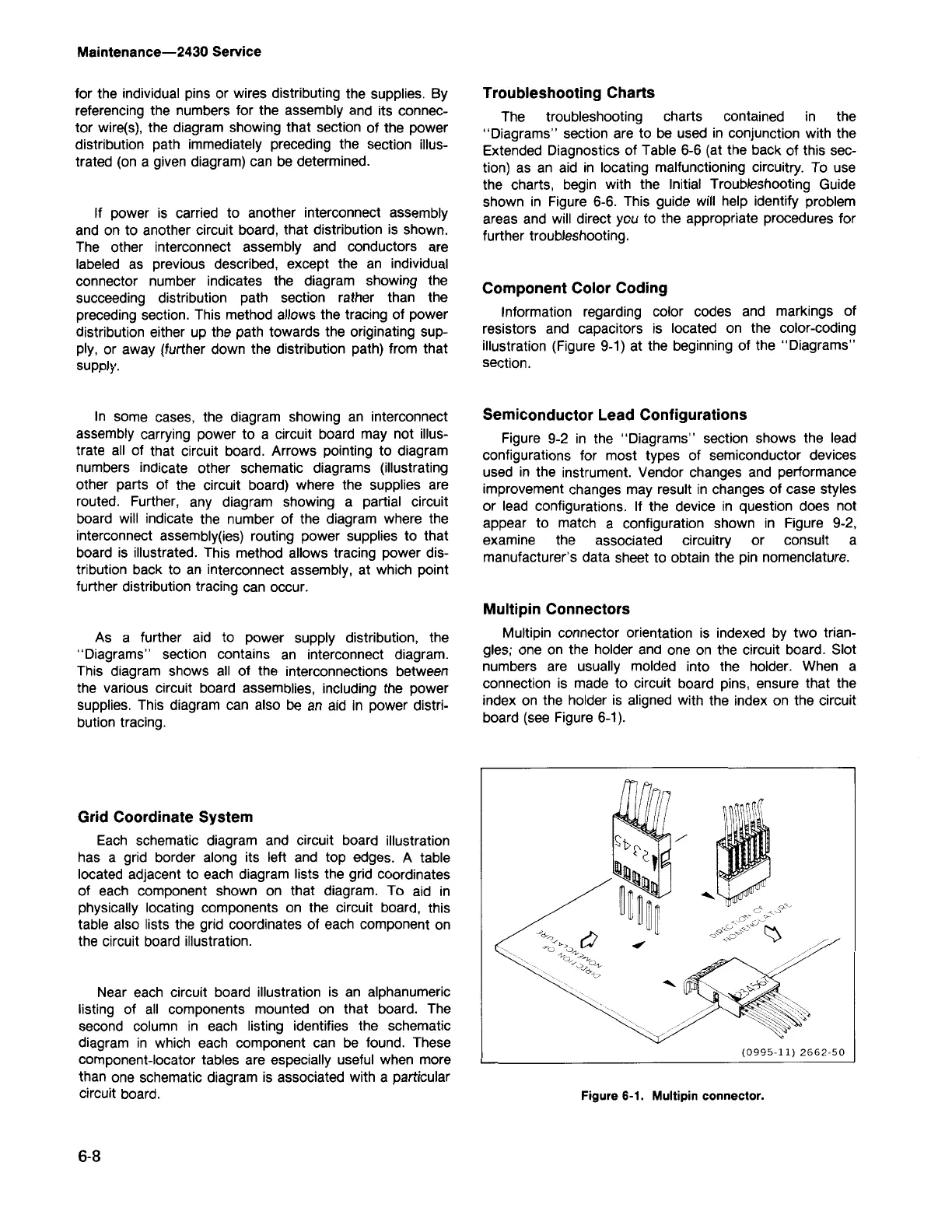
Figure 6-1. Multipin connector.
(0995-11) 2662-50
Multipin Connectors
Multipin connector orientation is indexed by two trian-
gles; one on the holder and one on the circuit board. Slot
numbers are usually molded into the holder. When a
connection is made to circuit board pins, ensure that the
index on the holder is aligned with the index on the circuit
board (see Figure 6-1).
Semiconductor Lead Configurations
Figure 9-2 in the "Diagrams" section shows the lead
configurations for most types of semiconductor devices
used in the instrument. Vendor changes and performance
improvement changes may result in changes of case styles
or lead configurations. If the device in question does not
appear to match a configuration shown in Figure 9-2,
examine the associated circuitry or consult a
manufacturer's data sheet to obtain the pin nomenclature.
Component Color Coding
Information regarding color codes and markings of
resistors and capacitors is located on the color-coding
illustration (Figure 9-1) at the beginning of the "Diagrams"
section.
Troubleshooting Charts
The troubleshooting charts contained in the
"Diagrams" section are to be used in conjunction with the
Extended Diagnostics of Table 6-6 (at the back of this sec-
tion) as an aid in locating malfunctioning circuitry. To use
the charts, begin with the Initial Troubleshooting Guide
shown in Figure 6-6. This guide will help identify problem
areas and will direct you to the appropriate procedures for
further troubleshooting.
6-8
Near each circuit board illustration is an alphanumeric
listing of all components mounted on that board. The
second column in each listing identifies the schematic
diagram in which each component can be found. These
component-locator tables are especially useful when more
than one schematic diagram is associated with a particular
circuit board.
Grid Coordinate System
Each schematic diagram and circuit board illustration
has a grid border along its left and top edges. A table
located adjacent to each diagram lists the grid coordinates
of each component shown on that diagram. To aid in
physically locating components on the circuit board, this
table also lists the grid coordinates of each component on
the circuit board illustration.
As a further aid to power supply distribution, the
"Diagrams" section contains an interconnect diagram.
This diagram shows all of the interconnections between
the various circuit board assemblies, including the power
supplies. This diagram can also be an aid in power distri-
bution tracing.
In some cases, the diagram showing an interconnect
assembly carrying power to a circuit board may not illus-
trate all of that circuit board. Arrows pointing to diagram
numbers indicate other schematic diagrams (illustrating
other parts of the circuit board) where the supplies are
routed. Further, any diagram showing a partial circuit
board will indicate the number of the diagram where the
interconnect assembly(ies) routing power supplies to that
board is illustrated. This method allows tracing power dis-
tribution back to an interconnect assembly, at which point
further distribution tracing can occur.
If power is carried to another interconnect assembly
and on to another circuit board, that distribution is shown.
The other interconnect assembly and conductors are
labeled as previous described, except the an individual
connector number indicates the diagram showing the
succeeding distribution path section rather than the
preceding section. This method allows the tracing of power
distribution either up the path towards the originating sup-
ply, or away (further down the distribution path) from that
supply.
for the individual pins or wires distributing the supplies. By
referencing the numbers for the assembly and its connec-
tor wire(s), the diagram showing that section of the power
distribution path immediately preceding the section illus-
trated (on a given diagram) can be determined.
Maintenance-2430 Service