NVRAMFailure
Anything that causes bad data to be stored in the
NVRAM (nonvolatile RAM) will cause a failure of one or all
of the 6000 level tests (CKSUM-NVRAM). Loss of stored
data from the NVRAM can cause seemingly unrelated
failures in the diagnostic tests. That is because all the fail
flags and calibration constants against which the current
testing is performed are stored in the NVRAM. Checking
against erroneous data and marking failures using bad
flags provides failure indications not related to a hardware
failure. Doing a "COLD START" (see "Special Diagnostic
Features") loads all the NVRAM locations with known
nominal values and removes the invalid data. This permits
SELF CAL and testing to be completed correctly. Replac-
ing the NV RAM or the Lithium storage battery requires a
COLD START to restore the NV RAM data to known
values. Even though the SPECIAL menu choices may be
disabled from front-panel access, a COLD START is done
automatically when the instrument finds no stored calibra-
tion constants during the first power-on after the
replacement.
Power-On/Self Diagnostics Test Failure
If the Self Diagnostics tests fail, either at power-on or
when called by the user from the front panel, the
"EXTENDED DIAGNOSTICS" mode will be entered. The
menu displayed in Extended Diagnostics permits the user
to determine which test(s) failed as a start in isolating the
fault to the problem area (see Table 6-6). A failure of tests
6000-9300 does not necessarily indicate a fatal instrument
fault. An abnormal power-off or transient power condition
may have prevented the orderly shutdown that normally
saves the data needed to return the scope to the operat-
ing state present at power-off. A failure of the SELF DIAG-
NOSTICS will also occur if the present temperature of the
scope is very different from the temperature during the last
SELF CAL. In the last case, the stored calibration con-
stants may not permit accurate measurements to be
made.
If you miss the code the first time (as is usual unless
you are expecting a failure), you must turn off the 2430
and turn it back on again to rerun the tests. It takes a little
practice to read the code from the LEOs.
8. After flashing out the coded number of the first
failed test, the diagnostics continues on with the remaining
tests, if able to. Any additional failures found, if any, will
NOT be flashed on the Trigger LEOs.
7. The fourth and final number of the failed test is 0,
and all the LEOs remain off between the number separa-
tors code.
6-28
6. The third number of the failed test (three) is shown
by turning on both the TRIG'D and the READY LEOs.
Their binary values are summed (1 + 2) to obtain the third
number of the failed test (three), and all the LEOs are
again lighted to separate the numbers.
5. The second number of the test number (one) is
shown by turning on the TRIG'D LED for the binary code
for 1, then all the LEOs are again turned on as the code
number separator.
4. For the first number of the failed test, the READY
LED turns on for a binary 2 (the failed test is in the 2000
level); all the LEOs are then turned on to separate the
numbers of the test code.
3. When the test failure occurs, all the Trigger LEOs
are lighted and held on for a period of time to indicate a
failure has been found; then the sequence of turning on
the LEOs begins for the code number of the failed test.
2. The TRIG'D LED is lighted to show that tests at
level 1000 are being run, then the READY LED is lighted
to show that 2000 level tests are being run. (Some test
levels are done very fast, and the LEOs do not remain on
long.)
1. All the LEOs are lighted at the beginning of the
power-on sequence to check that they all are capable of
being turned on.
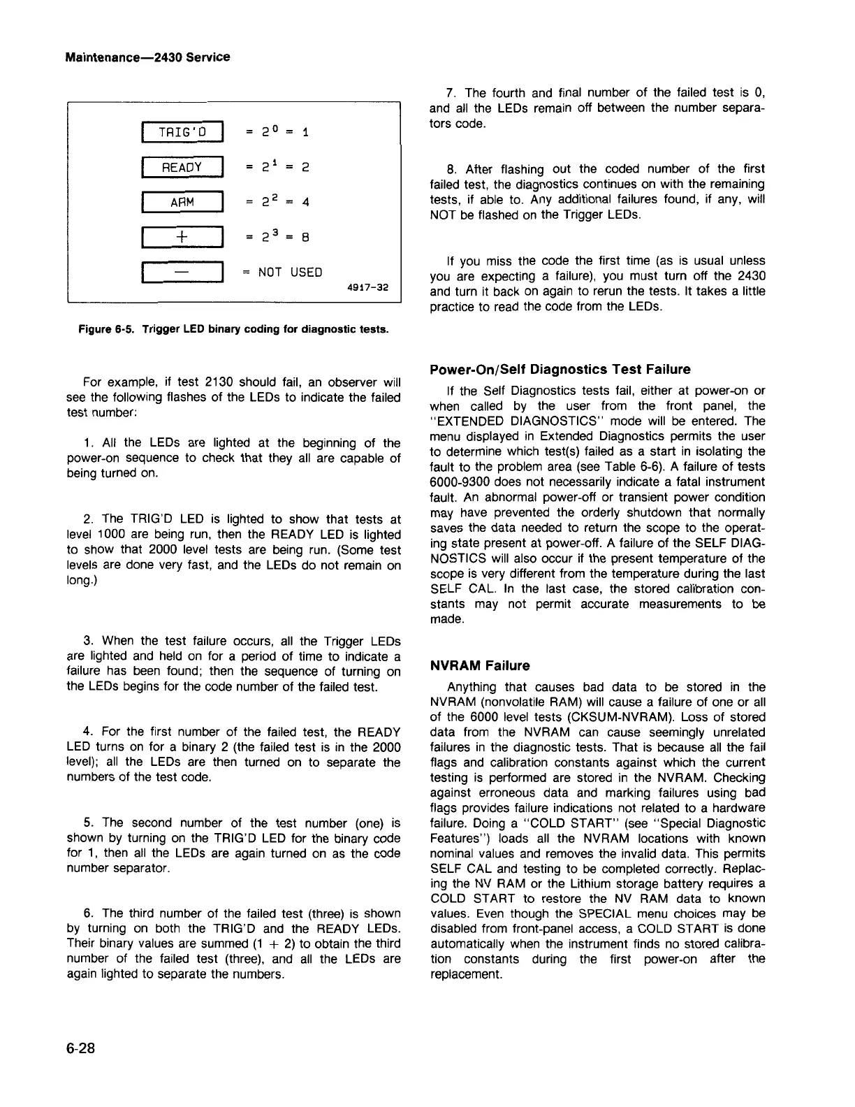
For example, if test 2130 should fail, an observer will
see the following flashes of the LEOs to indicate the failed
test number:
Figure 6-5. Trigger LEDbinary coding for diagnostic tests.
TRIG'D
2°
1
READY
21
2
ARM
22
4
+
23
=
8
=
NOT USED
4917-32
Maintenance-2430 Service