3-53
SHORT-PIPE MODE. A second acquisition mode,
Short-Pipe mode, is used at SEC/DIV settings 100 !1s/div
and slower. In Short-Pipe mode, the rjJ2A clock that
transfers samples down the input (A) register is disabled;
and instead, the TI (transfer into B array) clock shifts sam-
ples straight down the first register of the B array to the
output well. Sampling occurs at 1 MHz in Short-Pipe mode
(500 kHz each side of the CCD array) as the various
phase clocks are derived from the 2XPC clock. Trigger
delays are generated at the SDC (slow-delay clock) rate
since Short-Pipe mode connects the DELCLK output to
the SDC input. Since sampling is occurring at a 1 MHz
rate and the SEC/DIV is set so that a sample rate slower
than this is required, some of the samples must be dis-
carded. The discrepancy is resolved by Time Base Con-
troller by counting and discarding the proper number of
samples between those it allows to be saved. This allows
effective sample rates much lower than the actual 1 MHz
rate and, by routing the SDC signal to DELCLK, allows the
trigger delays to be counted in terms of effective sample
events.
Outputs TLO-TL4 (trigger location bits 0 through 4)
define the trigger location within
±
1/2 of a sample interval
and allow the extra samples taken at the beginning and
end of the CCD sample array contents to be discarded.
Defining and discarding these samples is done because
the trigger event may occur at any of 32 locations within
the two A registers. Outputs TL1-TL4 locate the trigger at
one of these 32 sample positions, allowing samples before
the start of the waveform to be discarded. Output TLO
defines trigger position within the sample interval to either
half of the interval (phase 1 side or phase 3 side) by sam-
pling the phase of the master clock when the trigger
occurred.
REV JUL 1987
Depending on trigger mode, the RTRIG (record trigger)
line will be asserted some time after JTRIG occurs. RTRIG
is synchronized to the B-register clock and is output to the
Time Base Controller on the SYNTRIG (synchronous
trigger) line, telling it to start counting post-trigger sam-
ples. The RTRIG also loads a register internal to U470
with the present sample count to locate the trigger event
(explained later). When the Time Base Controller has com-
pleted the post-trigger count, it will set SO (slow out) HI,
switching the Phase Clock Array mode from "Fast In" to
"Slow Out" mode. The various phase clocks are now
derived from the 1 MHz 2XPC clock (from the Time Base
Controller) instead of the 200/250 MHz master clock, and
samples are shifted out of the CCD arrays at the A/D
conversion rate.
Once enabled, the Trigger Logic Array begins counting
its predefined delay while samples continue to be acquired.
The DELCLK (delay clock) output to the Trigger Logic runs
at one-half the sample-clock rate, allowing the Trigger
Logic to complete any defined delay. When delay is done,
the JTRIG and RTRIG Signals may be generated. When
the JTRIG occurs, the RAMP and RAMP signals from the
Trigger Logic start the Jitter-Correction Ramps. The
JTRIG signal to U470 causes the TLO (trigger location-bit
0) bit to latch the phase (HI or LO) of the master clock,
defining which half of the cycle the trigger event occurred.
The internal slow-ramp logic circuitry of U470 becomes
enabled and, on the next two edges of the master clock,
asserts the two pairs of slow-ramp (SLRMP) outputs.
These outputs reverse the charge direction of the Jitter-
Correction Ramp circuits (diagram 12) and start the Jitter-
Correction Counters (diagram 13) on opposite edges of the
master clock. See those descriptions for further informa-
tion on trigger-jitter correction.
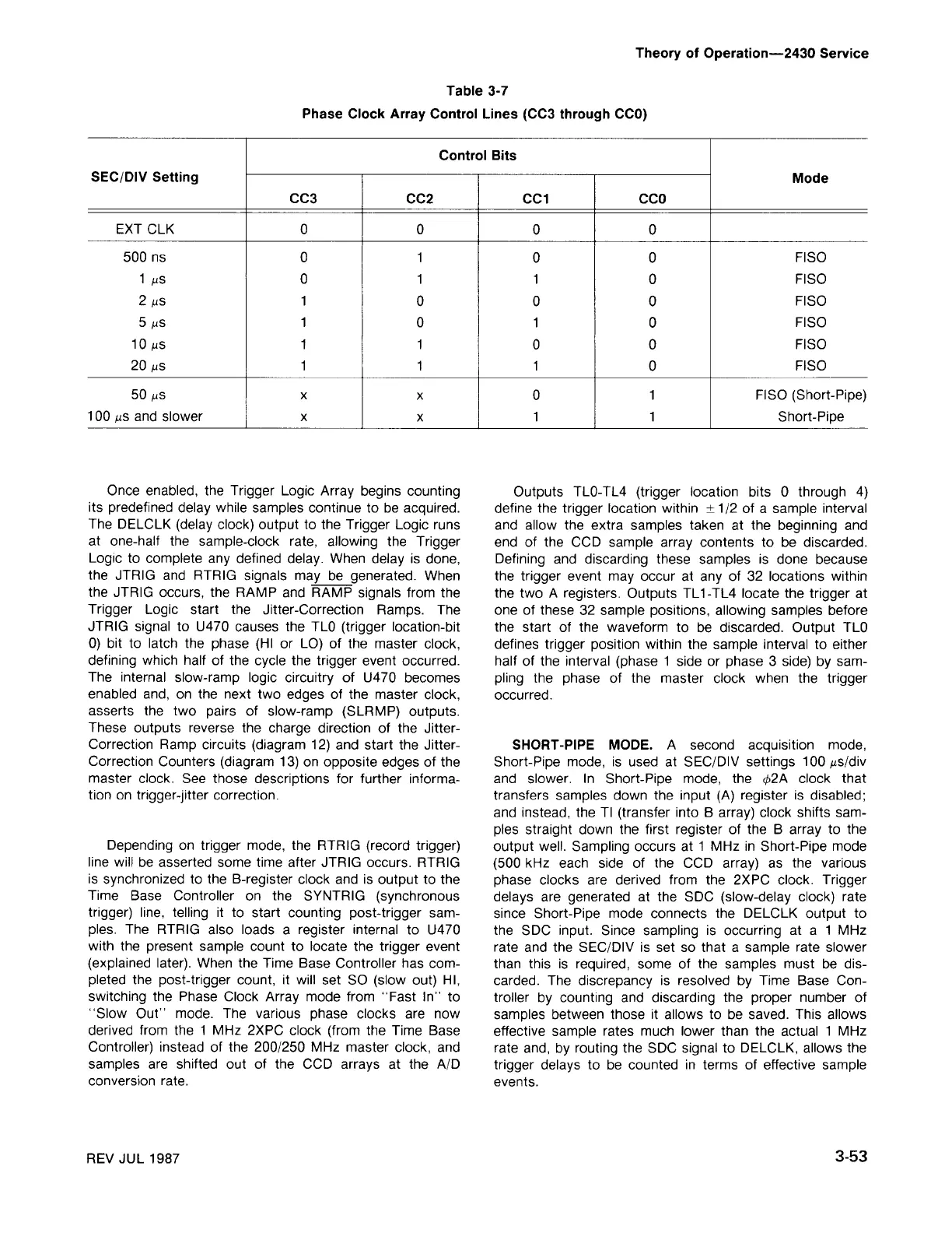
Control Bits
SEC/DIV Setting
Mode
CC3
CC2 CCl CCO
EXT CLK
0 0
0 0
500 ns
0 1
0 0
FISO
1 !1S
0 1 1
0
FISO
2 !1S
1
0
0 0
FISO
5 !1S
1
0 1
0
FISO
10 !1S
1 1
0 0
FISO
20 !1S
1 1 1
0
FISO
50 !1S
x
X
0
1
FISO (Short-Pipe)
100 !1Sand slower x
x 1 1 Short-Pipe
Table 3-7
Phase Clock Array Control Lines (CC3 through CCO)
Theory of Operation-2430 Service