REV DEC 1986
4-8
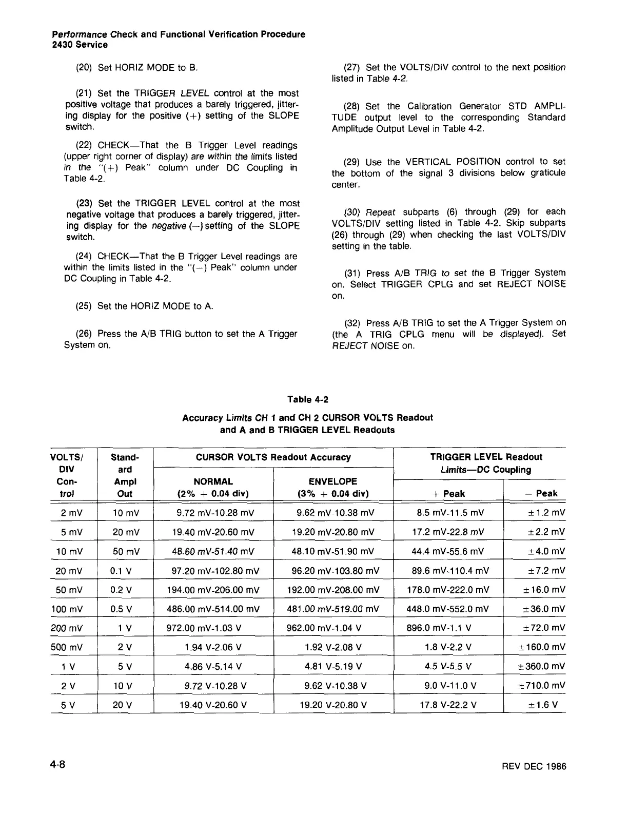
VOLTS/ Stand- CURSORVOLTS Readout Accuracy
TRIGGER LEVEL Readout
DIV ard
Limits-DC Coupling
Con- Ampl NORMAL ENVELOPE
trol Out (2% + 0.04 div) (3% + 0.04 div)
+ Peak
- Peak
2 mV 10 mV
9.72 mV-10.28 mV
9.62 mV-10.38 mV
8.5 mV-11.5 mV
±1.2 mV
5 mV 20 mV
19.40 mV-20.60 mV 19.20 mV-20.80 mV 17.2 mV-22.8 mV
±2.2 mV
10 mV
50 mV 48.60 mV-51.40 mV
48.10 mV-51.90 mV 44.4 mV-55.6 mV
±4.0 mV
20 mV 0.1 V 97.20 mV-l02.80 mV 96.20 mV-103.80 mV 89.6 mV-ll0.4 mV
±7.2 mV
50 mV 0.2 V 194.00 mV-206.00 mV 192.00 mV-208.00 mV
178.0 mV-222.0 mV
±16.0 mV
100 mV 0.5 V 486.00 mV-514.00 mV 481.00 mV-519.00 mV
448.0 mV-552.0 mV
±36.0 mV
200 mV 1 V 972.00 mV-l.03 V 962.00 mV-l.04 V
896.0mV-l.1 V
±72.0 mV
500 mV
2V
1.94 V-2.06 V
1.92 V-2.08 V
1.8 V-2.2 V
± 160.0 mV
1 V 5V 4.86 V-5.14 V 4.81 V-5.19 V
4.5 V-5.5 V
±360.0 mV
2V 10 V 9.72 V-10.28 V 9.62 V-l0.38 V
9.0 V-ll.0 V
±710.0 mV
5V 20 V 19.40 V-20.60 V 19.20 V-20.80 V
17.8 V-22.2 V
±1.6 V
Table 4-2
Accuracy Limits CH 1 and CH 2 CURSORVOLTS Readout
and A and B TRIGGER LEVEL Readouts
(32) Press A/B TRIG to set the A Trigger System on
(the A TRIG CPLG menu will be displayed). Set
REJECT NOISE on.
(31) Press A/B TRIG to set the B Trigger System
on. Select TRIGGER CPLG and set REJECT NOISE
on.
(30) Repeat subparts (6) through (29) for each
VOLTS/DIV setting listed in Table 4-2. Skip subparts
(26) through (29) when checking the last VOLTS/DIV
setting in the table.
(29) Use the VERTICAL POSITION control to set
the bottom of the signal 3 divisions below graticule
center.
(28) Set the Calibration Generator STD AMPLI-
TUDE output level to the corresponding Standard
Amplitude Output Level in Table 4-2.
(27) Set the VOLTS/DIV control to the next position
listed in Table 4-2.
(26) Press the A/B TRIG button to set the A Trigger
System on.
(25) Set the HORIZ MODE to A.
(24) CHECK-That the B Trigger Level readings are
within the limits listed in the "( -) Peak" column under
DC Coupling in Table 4-2.
(23) Set the TRIGGER LEVEL control at the most
negative voltage that produces a barely triggered, jitter-
ing display for the negative (-) setting of the SLOPE
switch.
(22) CHECK-That the B Trigger Level readings
(upper right corner of display) are within the limits listed
in the "(
+)
Peak" column under DC Coupling in
Table 4-2.
(21) Set the TRIGGER LEVEL control at the most
positive voltage that produces a barely triggered, jitter-
ing display for the positive
(+)
setting of the SLOPE
switch.
(20) Set HORIZ MODE to B.
Performance Check and Functional Verification Procedure
2430 Service