6-103
CH 1 ON
VOLTS/DIV (both) 100 mV
VARIABLE (both) CAL
COUPLING (both)
DC
5011(both) OFF
INVERT (both)
OFF
POSITION set to Midscreen
Display Mode YT
BANDWIDTH FULL
VERTICAL MODE Controls
STORAGE Mode
ACOUIRE
ACQUIRE Mode NORMAL
REPET
OFF
AVG Number
2
ENVELOPE Number
SAVE ON ~
OFF
REF1 through REF4
OFF
DELAY Controls
DELAY by EVENTS OFF
~ TIME
OFF
DELAY TIME
40,us
~ DELAY Time 0.0
DELAY EVENTS Nr.
STORAGE Mode Controls
MODE
A
A SEC/DIV 1 ms
EXT CLK Expansion
Factor
EXT CLK OFF
POSITION Waveform LIVE
POSITION Reference REF 1
POSITION set to Midscreen
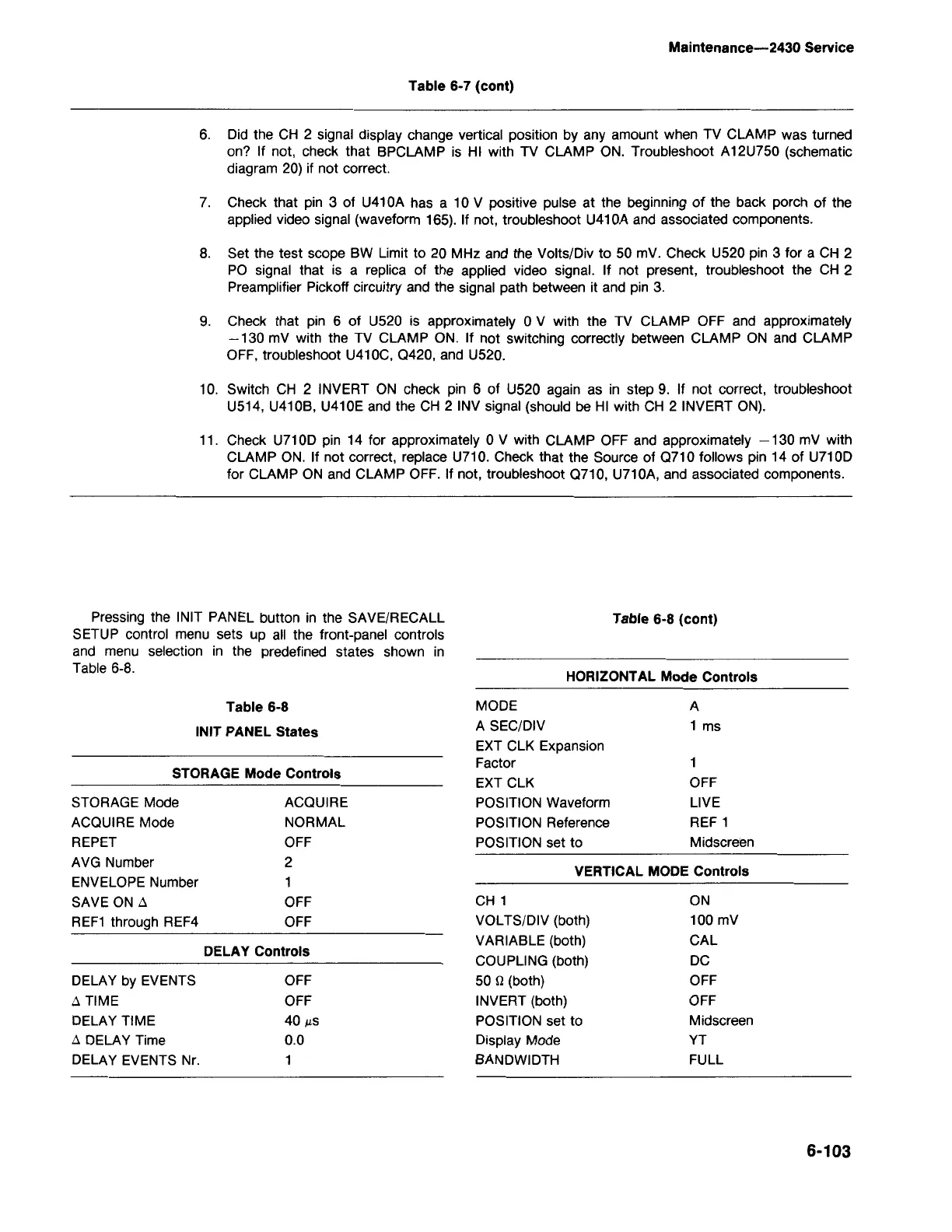
Table 6-8
INIT PANEL States
HORIZONTAL Mode Controls
Table 6-8 (cont)
Pressing the INIT PANEL button in the SAVE/RECALL
SETUP control menu sets up all the front-panel controls
and menu selection in the predefined states shown in
Table 6-8.
11. Check U710D pin 14 for approximately 0 V with CLAMP OFF and approximately -130 mV with
CLAMP ON. If not correct, replace U710. Check that the Source of 0710 follows pin 14 of U710D
for CLAMP ON and CLAMP OFF. If not, troubleshoot 0710, U710A, and associated components.
10. Switch CH 2 INVERT ON check pin 6 of U520 again as in step 9. If not correct, troubleshoot
U514, U410B, U410E and the CH 2 INV signal (should be HI with CH 2 INVERT ON).
9. Check that pin 6 of U520 is approximately 0 V with the TV CLAMP OFF and approximately
-130 mV with the TV CLAMP ON. If not switching correctly between CLAMP ON and CLAMP
OFF, troubleshoot U410C, 0420, and U520.
8. Set the test scope BW Limit to 20 MHz and the Volts/Div to 50 mV. Check U520 pin 3 for a CH 2
PO signal that is a replica of the applied video signal. If not present, troubleshoot the CH 2
Preamplifier Pickoff circuitry and the signal path between it and pin 3.
7. Check that pin 3 of U410A has a 10 V positive pulse at the beginning of the back porch of the
applied video signal (waveform 165). If not, troubleshoot U410A and associated components.
6. Did the CH 2 signal display change vertical position by any amount when TV CLAMP was turned
on? If not, check that BPCLAMP is HI with TV CLAMP ON. Troubleshoot A12U750 (schematic
diagram 20) if not correct.
Table 6-7 (cont)
Maintenance-2430 Service