6-23
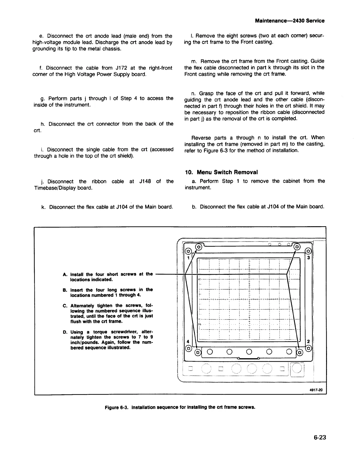
Figure 6-3. Installation sequence for installing the crt frame screws.
r=w
rv
()
o 'rjJ
'0"
l@o
r
3'
!
1
I
I
I
A. Install the four short screws at the
1
locations indicated.
B.
Insert
the
four long screws in the
locations numbered 1 through 4.
I
\
Ii
I
;
i\
C.
Alternately tighten the screws, foI-
I
I ,
lowing the numbered sequence illus-
Ii
,
-;
\
trated, until the face of the crt is just
I
flush with the crt frame.
I
~I Y
;
1
!
j
\
i
t
D.
Using a torque screwdriver, alter-
:
I
i
1
l_ ._l j
nately tighten the screws to 7 to 9
!
4 \
:
inch/pounds. Again, follow the num-
2
,
-X
v-.
bered sequenceillustrated.
@~
0
0
0 0
O~~
i
I
_ - - _
~
C ~ )
W~~~
<:»
-
-j
.:»
4917·20
b. Disconnect the flex cable at J104 of the Main board.
10. Menu Switch Removal
a. Perform Step 1 to remove the cabinet from the
instrument.
Reverse parts a through n to install the crt. When
installing the crt frame (removed in part m) to the casting,
refer to Figure 6-3 for the method of installation.
n. Grasp the face of the crt and pull it forward, while
guiding the crt anode lead and the other cable (discon-
nected in part
f)
through their holes in the crt shield. It may
be necessary to reposition the ribbon cable (disconnected
in part
j)
as the removal of the crt is completed.
m. Remove the crt frame from the Front casting. Guide
the flex cable disconnected in part k through its slot in the
Front casting while removing the crt frame.
I.
Remove the eight screws (two at each corner) secur-
ing the crt frame to the Front casting.
Maintenance-2430 Service
k. Disconnect the flex cable at J104 of the Main board.
j.
Disconnect the ribbon cable at J148 of the
Timebase/Display board.
i. Disconnect the single cable from the crt (accessed
through a hole in the top of the crt shield).
h. Disconnect the crt connector from the back of the
crt.
g. Perform parts
j
through I of Step 4 to access the
inside of the instrument.
f. Disconnect the cable from J172 at the right-front
corner of the High Voltage Power Supply board.
e. Disconnect the crt anode lead (male end) from the
high-voltage module lead. Discharge the crt anode lead by
grounding its tip to the metal chassis.