Reverse parts b through I to reinstall the Attenuator.
When performing part b, reverse parts b through s of Step
4 to reinstall the front panel and secure the
Timebase/Display board and Front Panel assembly to the
instrument.
I.
Gently lift the Attenuator straight up from the Main
board until the Attenuator pins clear their Main board
plugs underneath the Attenuator assembly. Lift the rear of
the Attenuator assembly up and towards the rear of the
instrument until the Attenuator clears the braided shield
cable mounted in the front casting.
k. Grasp the front end of the Attenuator assembly by
its BNC connector and the rear end by the rear edge of
the Attenuator shield.
j.
Remove the two screws securing the small bar to
the bottom of the front casting.
i. Remove the two screws (one is immediately lower
left and the other upper right of the associated input BNC
connector) securing the Attenuators to the front casting.
h. Unplug the multipin connector from the Main board
(at P147 for the CH 1 and P146 for the CH 2 Attenuator).
g. Unsolder the two Attenuator output leads from the
variable-capacitor lead and the resistor-capacitor pair lead
exposed in part f.
f. Remove the two screws securing the rear Attenuator
shield to the heatsink. Remove the small shield.
e. Rotate the Timebase/Display board to its mounting
position and temporarily secure it by rotating the two black
retaining lugs 1/2 turn clockwise to lock them. The two
retaining latches are located near the left-front and left-
rear corners of the Timebase/Display board.
d. Insert the tip of a screwdriver through the hole in
the Low Voltage Power Supply board that is directly above
the Attenuator to be removed. Remove the screw securing
the rear of the Attenuator to the Main Board.
c. Insert the tip of a short screwdriver through the
large slot in the front casting (above and right of the asso-
ciated input BNC connector). Remove the screw securing
the front of the Attenuator to the Main board.
6-24
b. Perform parts b through s of Step 4 to access the
inside of the instrument. Skip parts n, p, and q. When per-
forming part r of Step 4, route the cable disconnected in
part o.
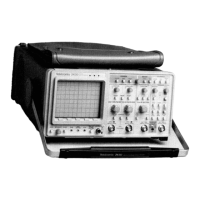
12. Attenuator Removal Procedure
a. Perform Step 1 to remove the cabinet from the
instrument.
Reverse parts a through d to install the Scale Illumina-
tion board to the instrument.
d. Separate the Scale Illumination board from the light
reflector to complete the disassembly.
c. Remove the Scale Illumination board and the
attached light reflector while guiding the cable (discon-
nected in part b) through its hole in the Front casting.
b. Disconnect the Scale Illumination board cable from
J106 (located near the front edge of the Main board).
11. Scale Illumination Board Removal
a. Perform parts a through e of Step 10.
Reverse parts a through e to install the Menu switch to
the crt frame and the frame to the instrument. Use care to
align the switch to the locating studs on the crt frame
when pressing the switch back on the frame.
f. Pull the switch through the hole in the crt frame to
complete the removal.
e. Carefully pull the adhesive-backed switch from the
front of the crt frame.
d. Perform parts k through m of Step 9 to remove the
crt frame from the instrument.
c. Perform parts c through i of Step 4 to remove the
trim band from the instrument.
Maintenance-2430 Service

 Loading...