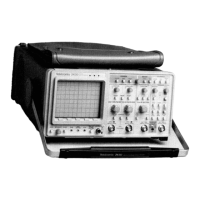
REV DEC 1986
d. Remove the anode lead from the retaining hook that
secures it to the Main chassis.
WARNING
I
The crt anode lead may retain a high-voltage charge
after the instrument is powered off. To avoid elec-
trical shock, ground the crt anode lead to the metal
chassis after disconnecting the plug. Reconnect and
disconnect the anode-load plug several times,
grounding the anode lead to chassis ground each
time it is disconnected to fully dissipate the charge.
c. Remove the implosion shield from the crt faceplate.
b. Perform parts c through i of Step 4 to remove the
trim band from the instrument.
a. Perform Step 1 to remove the cabinet from the
instrument.
Use care when handling a crt. Breakage of the crt
may cause high-velocity scattering of glass frag-
ments (implosion). Protective clothing and safety
glasses (preferably a full-face shield) should be worn.
Avoid striking the crt on any object which may cause
it to crack or implode. When storing a crt, place it in
a protective carton of set it face down on a smooth
surface in a protected location. When stored face
down, it should be placed on a soft, nonabrasive
surface to prevent the crt face plate from being
scratched.
9. Cathode Ray Tube Removal
I
WARNING
I
Reverse parts a through p to assemble the Low Volt-
age Power Supply assembly and secure it to the instru-
ment. Take care to fit the board to the channel notches
when reinstalling the board.
p. Pull the board towards the front of the instrument
(until its rear edge clears the two channel notches) while
lifting upwards to complete the removal of the assembly.
6-22
o. Grasp the front of the Low Voltage Power Supply
bracket and lift up until the Low Voltage Power Supply
board is clear of the retaining latches unlocked in part m.
n. Carefully route the disconnected cables away from
the top side of the Low Voltage Power Supply assembly.
m. Remove the mounting screw securing the Low Volt-
age Power Supply assembly to the Main chassis. The
screw is located near the right-front corner of the board.
I.
Using a 7/32 inch nutdriver, rotate the two black
retaining latches (near the left and right front corners of
the Low Voltage Power Supply board) 1/4 tum counter-
clockwise to unlock them. Repeat for the two latches
located near the middle of the right and left edges of the
board.
k. Disconnect the four cable connectors from P30,
P60, P70, and
pao
(located near the rear of the Low Volt-
age Power Supply board). Note the color coding of the
cables to guide in reconnection of same.
J.
Lift the cover off the Low Voltage Power Supply
bracket to remove.
i. Remove the two screws securing the cover to the
Rear chassis. One screw is located immediately below the
GPIB Connector, the other immediately below the
PLOTIER X OUTPUT BNC.
h. Remove the screw securing the cover to the Center
chassis.
g. Remove the six screws and two extension posts
securing the Low Voltage Power Supply cover (hereafter
referred to as "the cover") to the Low Voltage Power
Supply bracket.
f. Disconnect the flex cable connector from J207 at the
left front corner of the Processor board.
e. Disconnect the ribbon cable connectors at J102
(right front corner of the Low Voltage Power Supply Sup-
ply board) and J166 (left front corner of the same board).
d. Perform parts
j
through I of Step 4 to access the
inside of the instrument.
Maintenance-2430 Service

 Loading...