4-19
u. Repeat parts e through r to check the EXT 2 trigger
source, setting EXT2 -;- 5 and EXT 2 in parts m and q,
respectively.
t. Select TRIGGER SOURCE and set EXT 1:2 to 2.
Select TRIGGER CPLG.
S.
Move the leg of the Dual-Input Connector from the
EXT TRIG 1 input to the EXT TRIG 2 input.
r. Repeat parts f through q to check the trigger sensi-
tivity for each test frequency in Table 4-4. Use the Func-
tion Generator for frequencies below 50 MHz; use a Lev-
eled Sine-Wave Generator for frequencies equal to or
above 50 MHz.
q. Select EXT TRIG GAIN and set EXT 1 back on.
Reinstall the 5X attenuator in the test setup.
p. Set the generator output to the next Test Frequency
in Table 4-4.
o. If trigger sensitivity was near the specified limits for
the EXT1 or EXT1
-i-
5 sources with the trigger coupling
set to DC on, repeat parts i through n for all other cou-
pling settings in that test-frequency row, changing the
trigger coupling settings and generator amplitude as
required.
n. Select TRIGGER CPLG and repeat part
j
to check A
EXTl -;- 5 coupling.
m. Select EXT TRIG GAIN and set EXT1
-i-
5 on.
I.
Set CH 1 VOLTS/DIV for an on-screen display.
k. Remove the 5X attenuator from the test setup and
reconnect the setup as in part b.
j.
CHECK-For a stable, triggered display at the DC
trigger coupling setting. Press TRIGGER SLOPE to check
for both + and - slopes.
i. Set the output amplitude of the specified Test Fre-
quency to the level given in Table 4-4 for the A Trigger
System with DC Trigger Coupling.
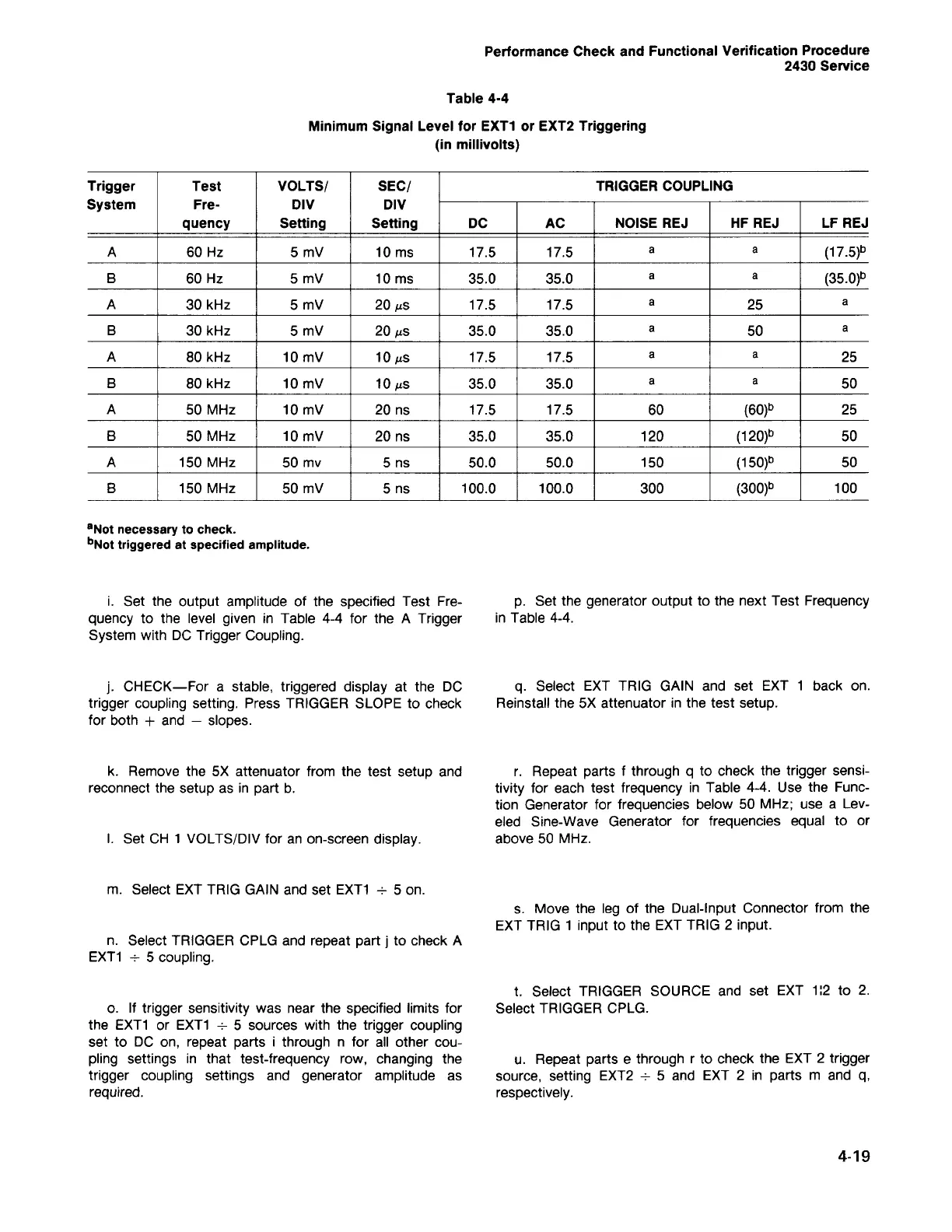
aNot necessary to check.
bNot triggered at specified amplitude.
Trigger Test VOLTS/ SEC/ TRIGGER COUPLING
System
Fre- DIV DIV
quency Setting Setting
DC AC
NOISE REJ HF REJ LF REJ
A
60 Hz 5 mV 10 ms 17.5 17.5
a a
(17.5)b
B
60 Hz
5 mV 10 ms 35.0 35.0
a
a
(35.0)b
A
30 kHz 5 mV
201ls
17.5 17.5
a
25
a
B
30 kHz 5 mV
201ls
35.0 35.0
a
50
a
A
80 kHz 10 mV
101ls
17.5 17.5
a a
25
B
80 kHz 10 mV
101ls
35.0 35.0
a a
50
A
50 MHz 10 mV 20 ns 17.5 17.5
60
(60)b
25
B
50 MHz 10 mV
20 ns 35.0 35.0 120
(120)b
50
A
150 MHz 50 mv
5 ns 50.0 50.0
150
(150)b
50
B
150 MHz 50 mV 5 ns 100.0 100.0
300
(300)b
100
Minimum Signal Level for EXT1 or EXT2 Triggering
(in millivolts)
Table 4-4
Performance Check and Functional Verification Procedure
2430 Service
 Loading...


