6-95
Chip Test
Address Position Within
Select Point Bus
Range (hex) the AF Period
SAVE
US80-8
WP
0OOO-lFFF
First 1/8th
DISP US70-13 WP
2000-2FFF Third 1/16th
DATI
US70-12 WP
3000-3FFF Fourth 1/16th
ACO
US70-11 WP
4000-4FFF Fifth 1/16th
CMD/TEMP
U2S0-8 WP
SOOO-S7FF Twelfth 1/32nd
COEFF
U2S0-11 WP
S800-SFFF Thirteenth 1/32nd
HMMIO
U870-6
BOTH
6000-6FFF Seventh 1/16th
NVRAM
U840-6 SYS
700O-77FF Sixteenth 1/32nd
SYSRAM
U840-3 SYS
7800-7FFF Seventeenth 1/32nd
ROMO.X
U890-4 SYS 8000-BFFF
Third 1/4th
ROM1
U890-S SYS COOO-FFFF
Last 1/4th
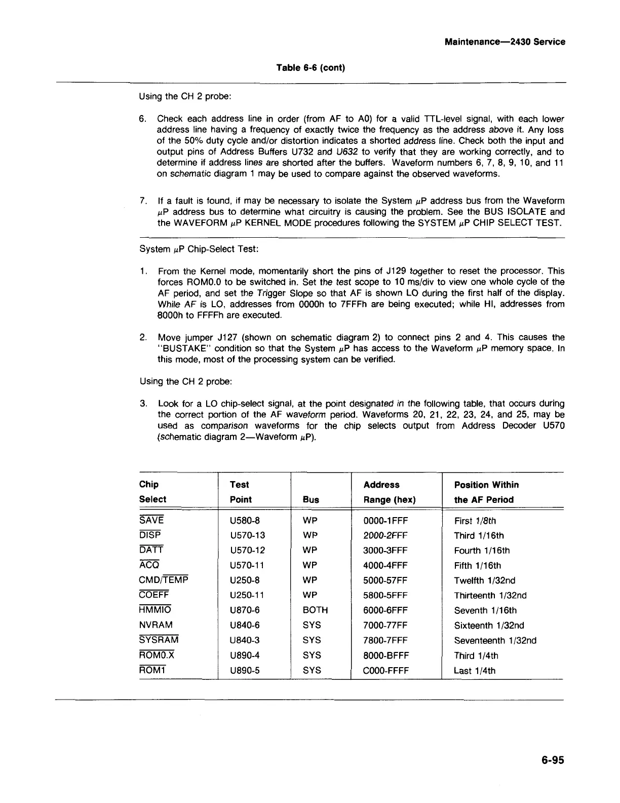
3. Look for a LO chip-select signal, at the point deSignated in the following table, that occurs during
the correct portion of the AF waveform period. Waveforms 20, 21, 22, 23, 24, and 2S, may be
used as comparison waveforms for the chip selects output from Address Decoder US70
(schematic diagram 2-Waveform .uP).
Using the CH 2 probe:
2. Move jumper J127 (shown on schematic diagram 2) to connect pins 2 and 4. This causes the
"BUSTAKE" condition so that the System .uPhas access to the Waveform .uPmemory space. In
this mode, most of the processing system can be verified.
1. From the Kernel mode, momentarily short the pins of J129 together to reset the processor. This
forces ROMO.Oto be switched in. Set the test scope to 10 ms/div to view one whole cycle of the
AF period, and set the Trigger Slope so that AF is shown LO during the first half of the display.
While AF is LO, addresses from OOOOhto 7FFFh are being executed; while HI, addresses from
8000h to FFFFh are executed.
System .uPChip-Select Test:
7. If a fault is found, if may be necessary to isolate the System .uPaddress bus from the Waveform
.uP address bus to determine what circuitry is causing the problem. See the BUS ISOLATE and
the WAVEFORM .uPKERNEL MODE procedures following the SYSTEM .uPCHIP SELECT TEST.
6. Check each address line in order (from AF to AO) for a valid TIL-level signal, with each lower
address line having a frequency of exactly twice the frequency as the address above it. Any loss
of the SO%duty cycle and/or distortion indicates a shorted address line. Check both the input and
output pins of Address Buffers U732 and U632 to verify that they are working correctly, and to
determine if address lines are shorted after the buffers. Waveform numbers 6, 7, 8, 9, 10, and 11
on schematic diagram 1 may be used to compare against the observed waveforms.
Using the CH 2 probe:
Table 6-6 (cont)
Maintenance-2430 Service

 Loading...


