Reference
370B User Manual
3-57
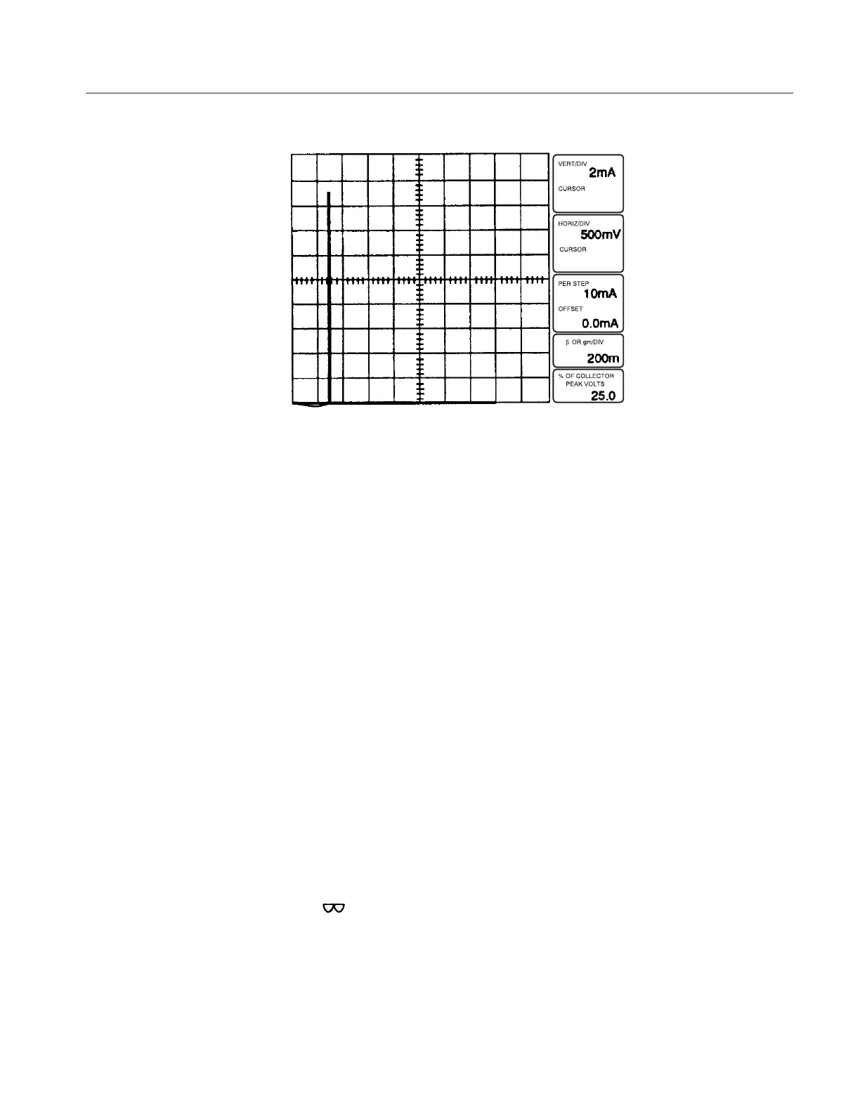
Figure 3-34: SiliconĆcontrolled Rectifier Curve
Common Measurements for Silicon Controlled Rectifiers.
Turn-on
The gate voltage or current at which the device turns on is measured by
applying a specified voltage between the anode and cathode terminals, using
the VARIABLE COLLECTOR SUPPLY control and applying current or
voltage steps in small increments to the gate with the STEP AMPLITUDE
control .
Forward Blocking Voltage
To measure the forward blocking voltage, set the CONFIGURATION to
BASE OPEN (or SHORT, depending on the specification) and turn the
VARIABLE COLLECTOR SUPPLY control clockwise until the device
switches to its low impedance state. The voltage at which switching occurs is
the forward blocking voltage.
Holding Current
Holding current is measured in the same manner as forward blocking
voltage. Holding current is the minimum current conducted by the device,
while operating in its low impedance state, without turning off.
Reverse Blocking Voltage
The reverse blocking voltage is measured the same way as the forward
blocking voltage, except that the Collector Supply POLARITY is set to
–
.