TM 11-6625-2735-14-1
Section 6—475 Service
SCHEMATIC DIAGRAMS AND OPTIONS 04 AND 07
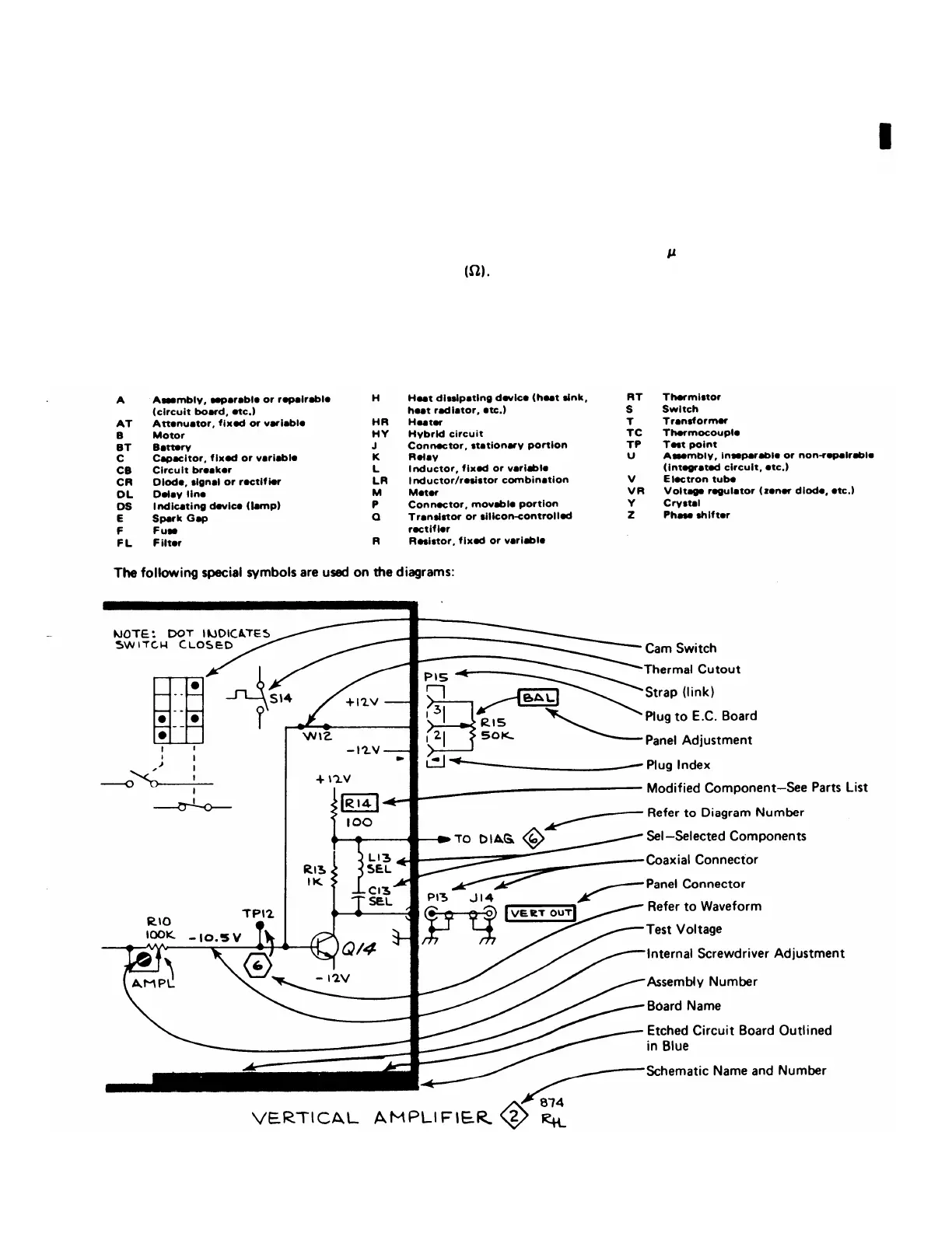
Symbols and Reference Designators
Electrical components shown on the diagrams are in the following units unless noted otherwise:
Capacitors =
Values one or greater are in picofarads (pF).
Values less than one are in microfarads ( F).
Resistors =
Ohms
Symbols used on the diagrams are based on USA Standard Y32.2-1967.
Logic symbology is based on MIL-STD-806B in terms of positive logic. Logic symbols depict the logic function performed
and may differ from the manufacturer’s data.
The following prefix letters are used as reference designators to identify components or assemblies on the diagrams.
Change 1 6-1
 Loading...


