TM 11-6625-2735-14-1
Sweep Control Integrated Circuit
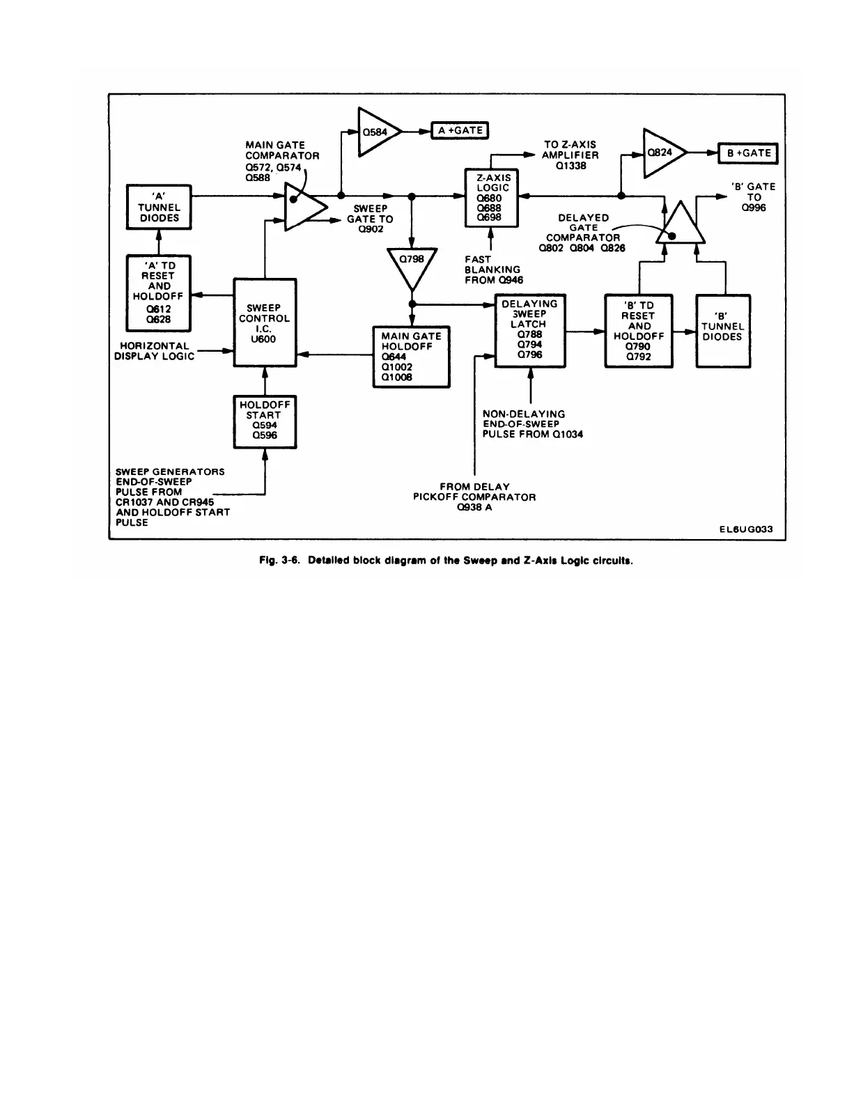
U600 is the Sweep Control Integrated Circuit. Several
functions are performed in this stage, depending on the
mode of operation of the instrument sweep generators.
The following is a brief explanation of the function
associated with each pin of the IC.
Pin 1.
This is the positive tunnel diode input. The signal
connected here comes from the A Firing TD in the A
Trigger Generator circuit. The voltage level switches from
0 to +0.5 volts and is compared with pin 2 internally.
Pin 2. This is the negative tunnel diode input. A fixed
DC level established by R602 and R603 provides the
reference for comparison with pin 1.
Pin 3. This is the positive tunnel diode output terminal.
In the AUTO mode of operation (TRIG MODE set to
AUTO) at the end of the holdoff time period, pin 1, pin 16
and pin 19 are LO, and pin 8 is HI. This causes the gate
level at pin 3 to step LO to turn Q574 on, which initiates a
sweep.
Pin 4. This is the negative tunnel diode output terminal;
connected to +5 volts in this application.
Pin 5. Input terminal for a negative 5 volts through
VR608 from the –8-volt supply.
Pin 6. This is the auto RC timing terminal. R609 and
C609 determine the amount of time between loss of trigger
signal and the generation of an auto gate at pin 3 when
TRIG MODE is set to AUTO.
Pin 7. This terminal lights the TRIG light when a
triggering gate has occurred, causing pin 1 to go HI.
Pin 8. This is the holdoff timing terminal. The time
between the end of an individual sweep and the start of the
next sweep is determined by RC components that affect
the time constant of voltage of pin 8. The TIME/DIV
control selects fixed components in the holdoff timing
circuit and the A TRIG HOLDOFF control allows a variable
holdoff setting in each position of the TIME/DIV control.
When pin 8 goes Hl, pin 17 will go LO and allow the trigger
tunnel diodes to fire on an incoming signal or generate an
auto gate in the Auto mode if pin 6 is HI.
3-13
 Loading...


