TM 11-6625-2735-14-1
3. If the spacers come out with the strip, remove them
from the stud pins for use on the new strip (spacers should
be replaced if they are damaged).
REPLACEMENT:
1. Place the spacers in the chassis holes.
2. Carefully press the studs of the strip into the spacers
until they are completely seated. If necessary, use a soft
mallet and tap very lightly, directly over the stud, to seat
the strip completely.
3. If the stud extends through the spacers, cut off the
excess.
4. Replace all components and connections. Observe
the soldering precautions given under Soldering Techni-
ques in this section.
Fuse Replacement.
Table 4-4 gives the rating, location,
and functions of the fuses used in this instrument.
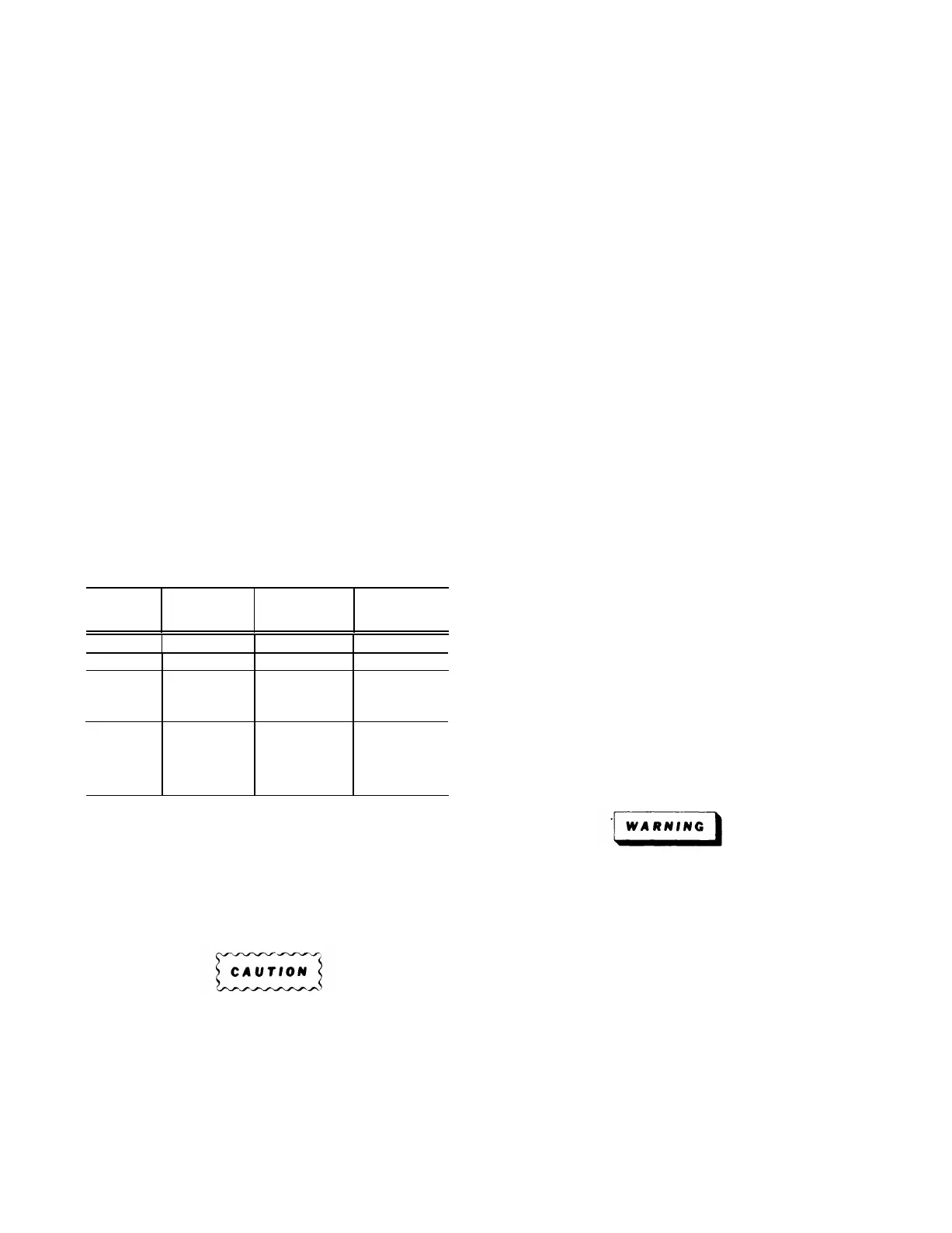
TABLE 4-4
Fuse Rating, Location and Functions
Circuit
Number
Rating
Location Function
F1401
1.5 A Fast
Rear Panel
115-volt line
F1401
0.75 A Fast Rear Panel
230-volt line
F1318
1.5 A Fast
Rear of Main
High
Interface
Voltage
Board
F1601
15 A Fast
Front of
Inverter
Inverter Input
Chassis
(Option 7
Only)
If a cam switch must be removed from a circuit board
the circuit board containing the cam switch must be
removed from the instrument. See the circuit-board
replacement part of this section for circuit board removal
instructions.
Disconnect the flexible coupling between cam switch
and variable controls. Remove two connecting screws
from each support block that holds the cam to the circuit
board. Carefully lift the cam assembly from the circuit
board and perform an inspection, cleaning or replacement
as intended.
Reassemble the cam-switch assembly by reversing the
previous process. Give careful attention to alignment and
spacing of support blocks as the cam is mated to its circuit
board. Do not bend circuit boards at any time in
reassembly and use a very low torque to tighten the
mounting screws (two fingers on the screwdriver is
enough torque).
Circuit Board Replacement
Occasionally it may be necessary to gain access to the
reverse side of a circuit board or to remove one circuit
board to gain access to another. The following procedures
outline the necessary steps to facilitate instrument dis-
assembly. Most of the connections to the circuit boards in
the instrument are made with pin connectors. However,
some connections are soldered to the board. Observe the
soldering precautions given under Soldering Techniques
given in this section.
Cam Switch Replacement. A complete cam switch is
actually a cam switch assembly. Each assembly consists
of a delrin-material cam that is rotated by a front-panel
knob and a set of contacts (mounted on an adjacent circuit
Always disconnect the instument from the power
board) that are actuated by the lobes on the cam.
source before atternptlng to remove circuit boards.
Repair of cam-type should be undertaken
on/y by experienced maintenance personnel. Switch
alignment and spring tension of the contacts must
be carefully maintained for proper operation of the
switch. For this reason, it is recommended that the
switch assembly be replaced as a unit.
To aid in identifying and locating circuit boards in the
instrument, see Fig. 4-5 for the Iocations of circuit boards.
In the following circuit-board replacement procedure,
determine the circuit board to be removed or replaced,
find the name of the board listed within this procedure,
and follow the removal or installation instructions. To aid
in identifying small components described in this
procedure, use the diagrams in Section 7, Mechanical Parts
List, in this manual.
4-22

 Loading...


