TM 11-6625-2735-14-1
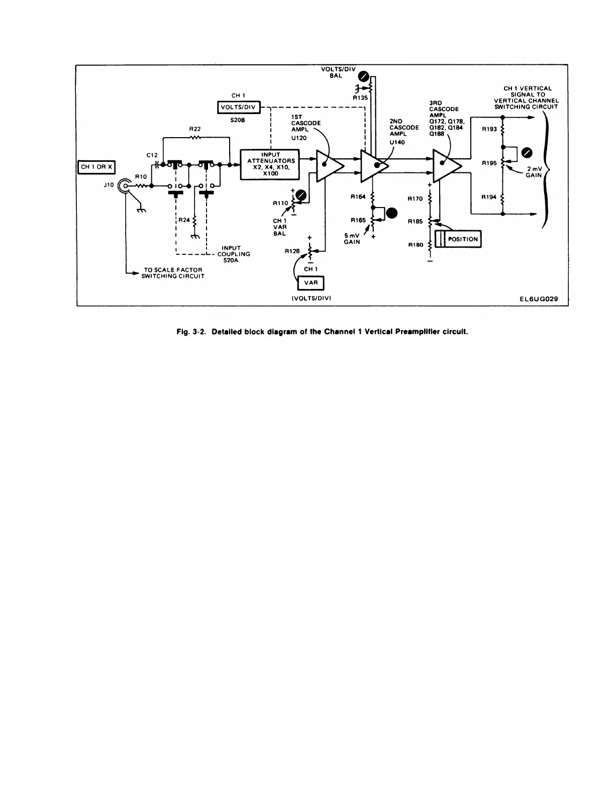
Input Coupling
Signals applied to the input connector can be AC
coupled, DC coupled, or internally disconnected from the
input to the Vertical Input Amplifier circuit. When Input
Coupling switch S20A is set for DC coupling, the input
signal is coupled directly to the Input Attenuator stage.
When AC coupled, the input signal passes through
capacitor C12. This capacitor prevents the DC component
of the signal from passing to the amplifier. In the GND
position, S20A opens the signal path and connects the
input of the amplifier to ground through R24. This
provides a ground reference without the need to dis-
connect the applied signal from the input connector.
Resistor R22, connected across the input coupling switch,
allows C12 to be pre-charged in the ground position,
which prevents generation of large voltage transients at
the input to the amplifier and allows the trace to remain on
screen when switched to the AC position.
Input Attenuator
The effective overall deflection factor of each channel
of the 475 is determined by the appropriate VOLTS/DIV
switch setting. The basic deflection factor of the Vertical
Defection System is 5 millivolts/division of CRT deflec-
tion. To achieve the deflection factor values indicated on
the front panel, precision attenuators are switched into the
circuit and, in the 2 mV position, the gain of the Second
Cascode Amplifier stage is increased.
For the VOLTS/DIV switch positions above 5 mV,
attenuators are switched into the circuit singly or in pairs
to help produce the vertical deflection factors indicated.
These attenuators are frequency-compensated voltage
dividers. In addition to providing constant attenuation at
all frequencies within the bandwidth of the instrument, the
Input Attenuators are designed to maintain the same input
RC characteristics for each setting of the VOLTS/DIV
switch. Each attenuator contains an adjustable series
capacitor to provide correct attenuation at high frequen-
cies and an adjustable shunt capacitor to provide correct
input capacitance.
NOTE
Each attenuator is a hybrid encapsulated plug-in
assembly; therefore, replacement of individual comp-
pnents within the attenuator are not possible.
Should defects occur, the attenuator must be replac-
ed as a unit.
First Cascode Amplifier
The first amplifier stage in the Channel 1 Preamplifier
circuit is hybrid circuit U120. U120 basically consists of an
integrated emitter-coupled, push-pull, cascode amplifier
and two discrete field-effect transistors (FET) mounted on
a ceramic substrate with the thick-film resistors. The stage
is a paraphase amplifier and converts the single-ended
input signal to push-pull output signals. CR104 and
CR107 provide protection for the input to U120 if large
negative-going signals or DC levels are applied to the CH
1 OR X input connector.
3-5
 Loading...


