TM 11-6625-2735-14-1
Second IC Amplifier
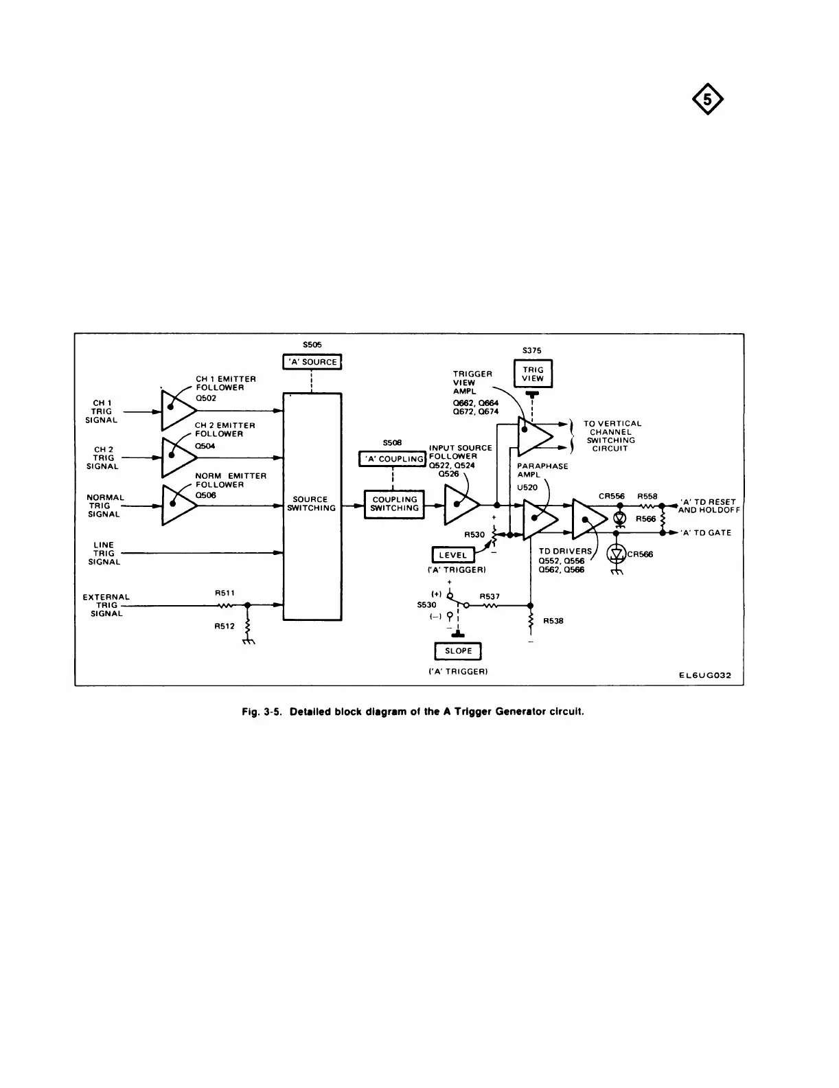
A TRIGGER GENERATOR
The second amplifier stage in the Vertical Output
Amplifier is integrated circuit U470. U470 is a multi-stage
General
cascode amplifier cell. The input signal is applied to pins 1
and 5 with the inverted output signal taken from pins 9 and
12. Pins 2 and 4 are emitter connections. Some of the
components connected between pins 2 and 4 provide
slower time constants to compensate for signal rolloff that
occurs in the delay line, while the remaining components
compensate for thermal considerations in the stage. The
Output Bias adjust (R487) sets the DC levels within the
stage to optimize the operating performance of U470. The
output signal from U470 connects directly to the deflec-
tion plates of the CRT.
The A Trigger Generator circuit produces the trigger
pulse used to start the Sweep Generator circuit that
provides the A portion of the CRT display. The trigger
pulse is derived from the internal trigger signal from the
vertical deflection system, an external signal connected to
the external trigger input connector, or a sample of the line
voltage connected to the instrument. Controls are provid-
ed to select trigger level, slope, coupling, and source. Fig.
3-5 shows a detailed block diagram of the A Trigger
Generator circuit. A schematic of this circuit is shown on
Diagram 5 at the rear of this manual.
3-10

 Loading...


