TM 11-6625-2735-14-1
CONTROLS AND CONNECTORS
General
The major controls and connectors for operation of the
475 are located on the front panel of the instrument. A few
auxiliary functions are provided on the rear panel. Fig. 2-2
shows the front and rear panels of the 475. A brief
description of each control and connector is given here.
More detailed operating information is given in the 475
Oscilloscope Operators Manual.
Cathode-Ray Tube (CRT) and Display
BEAM FINDER
Limits the display to within the
graticule area, independently of
display position or applied
signals and sets the display
brightness to a normal viewing
level.
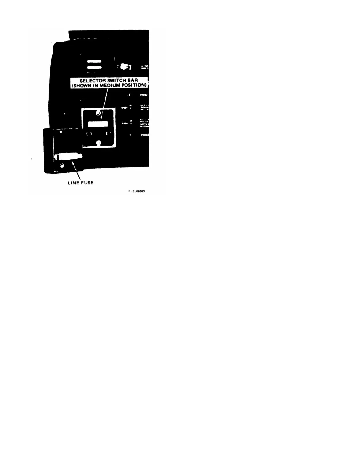
Fig. 2-1. Reguiating Range Selector and Line Fuse.
INTENSITY
FOCUS
Controls brightness of the dis-
play.
Provides adjustment for op-
timum display definition.
5. Check Table 2-1 for the recommended range posi-
tion of the Range Selector Switch Bar (see Figure 2-1).
SCALE ILLUM Controls graticule brightness.
Select a range which is centered about the average line
voltage to which the instrument is to be connected. The
middle position (“M”) is a typical setting.
ASTIG
Screwdriver adjustment used in
conjunction with the FOCUS
control to obtain a well-defined
6. If necessary, gently pull out the Range Selector
display. Does not require read-
Switch Bar, slide the bar to the desired position and plug it
justment in normal use.
back in.
TRACE ROTATION
Screwdriver adjustment to align
7. Install the cover on the Regulating Range Selector
the trace with the horizontal
assembly and gently tighten the 2 captive screws.
graticule lines.
8. Connect the instrument to the recommended power Vertical Deflection System (Channel 1 & Channel 2)
source, pull the instrument POWER switch to ON and
POSITION Controls the vertical position of
begin usage of the 475 Oscilloscope.
the trace. In the X-Y mode of
Options
Options are available to alter oscilloscope performance
to meet particular applications. A number in either MOD
slot (see instrument rear panel) indicates that the instru-
ment contains an option.
Refer to the Option section in this manual to find any
change in operating instructions as a result of the option.
CH1 OR X
operation, the CH 2 control
positions on the Y-axis (ver-
tically) and the CH 1 POSITION
control positions on the X-axis
(horizontally).
Input connector for Channel 1
deflection signals or X-axis
deflection in the X-Y mode of
operation.
2-2

 Loading...


