going signal peaks, Q1362 is pulsed on to renew the
charge on C1358. CR1367 provides protection to the Z-
Axis Amplifier circuitry in the event of short duration
arcing in the CRT High-Voltage Power Supplies.
In the 0.1 s, 0.2 s, 0.5 s, and X-Y positions of the
TIME/DIV switch, the anode of CR1337 is connected to
ground. This limits how negative the operating level at the
emitter of Q1338 can go to reduce the unblinking
capabilities of the amplifier, thereby reducing the
possibility of inadvertently burning the CRT phosphor.
When the BEAM FINDER pushbutton is pressed, –8 volts
is connected to the junction of R1342 and R1346. This
biases Q1338 off which in turn causes CR1343 to be
reverse biased. Now the output of the Z-Axis Amplifier is
isolated from all of the circuit’s normal signal inputs. The
output level of the amplifier is set at a nearly fixed level
(approximately +25 volts) determined by the parallel value
of R1343 and R1346 divided into the feedback resistance
of the amplifier. This sets the sweep intensity to a normal
viewing level.
CALIBRATOR
General
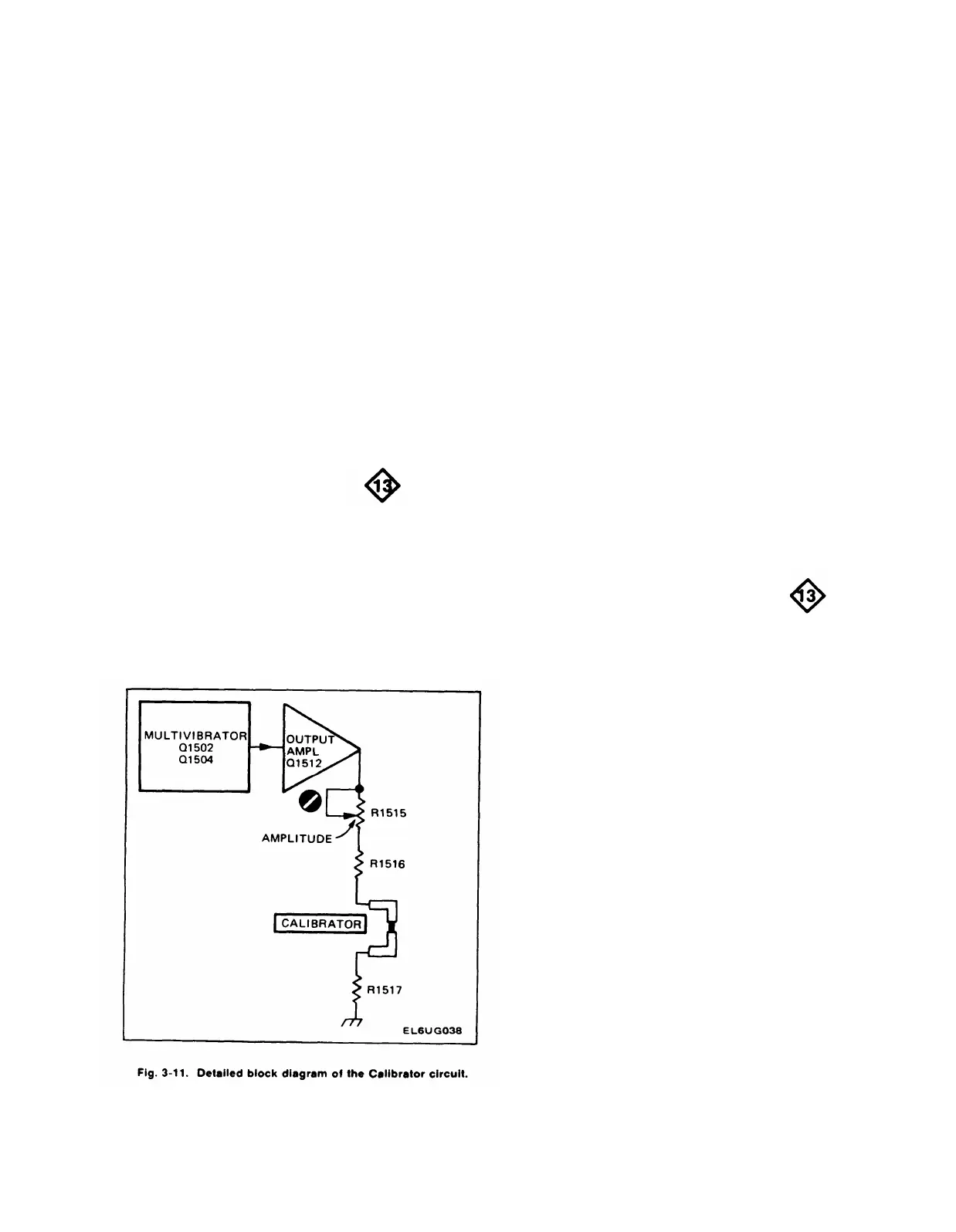
The Calibrator circuit produces a square-wave output
signal with accurate voltage and current amplitudes. This
output is available as a voltage or current at the
CALIBRATOR current loop on the instrument front panel.
Fig. 3-11 shows a detailed block diagram of the Calibrator
circuit. A schematic of this circuit is shown on Diagram 13
at the rear of this manual.
TM 11-6625-2735-14-1
Multivibrator
Q1502 and Q1504 along with their associated circuitry
compose an astable multivibrator. The basic frequency of
the multivibrator is approximately one kilohertz and is
essentially determined by the RC combination of C1505,
R1502, and R1504. Q1502 and Q1504 alternately conduct,
producing a square-wave signal that is taken from the
collector of Q1504.
Output Amplifier
The output signal from the Multivibrator overdrives
Output Amplifier Q1512 to produce a square wave at the
output. When the base of Q1512 goes positive, Q1512 is
cut off and the collector level drops down to ground. When
the base goes negative, Q1512 biased into saturation and
the collector of Q1512 rises positive to about +5 volts.
Amplitude adjustment R1515 adjusts the resistance
between the collector of Q1512 and ground to determine
the amount of current allowed to flow, which in turn
determines the voltage developed across R1517.
FAN MOTOR CIRCUIT
General
The fan motor used in the 475 is a brushless DC motor
using Hall Effect devices. The fan motor control circuitry
varies the rotational speed of the fan as the operating
temperature changes.
Two Hall Effect devices inside the motor, and 4
transistors U8061A, B, C, and D (U1690-A-D for early
SN) compose a sine-wave generator to drive the motor
windings. Each of the 4 transistors is controlled by 1/2 of a
Hall element to generate 1/4 of the sine-wave cycle.
As the ambient temperature increases, the value of
thermistor RT8038 (RT1696 for early SN) decreases. This
biases Q8067 (Q1698 for early SN) on harder to conduct
more current through the Hall devices and turn the motor
winding control transistor on harder. The harder the
transistor is conducting, the faster the fan rotates.
Typical fan speed variation with ambient temperature
is:
–15°C, approx. 800 RPM
+25°C, approx. 2000 RPM
+55°C, approx. 3100 RPM
3-27/(3-28 blank)
 Loading...


