TM 11-6625-2735-14-1
Channel Switch IC
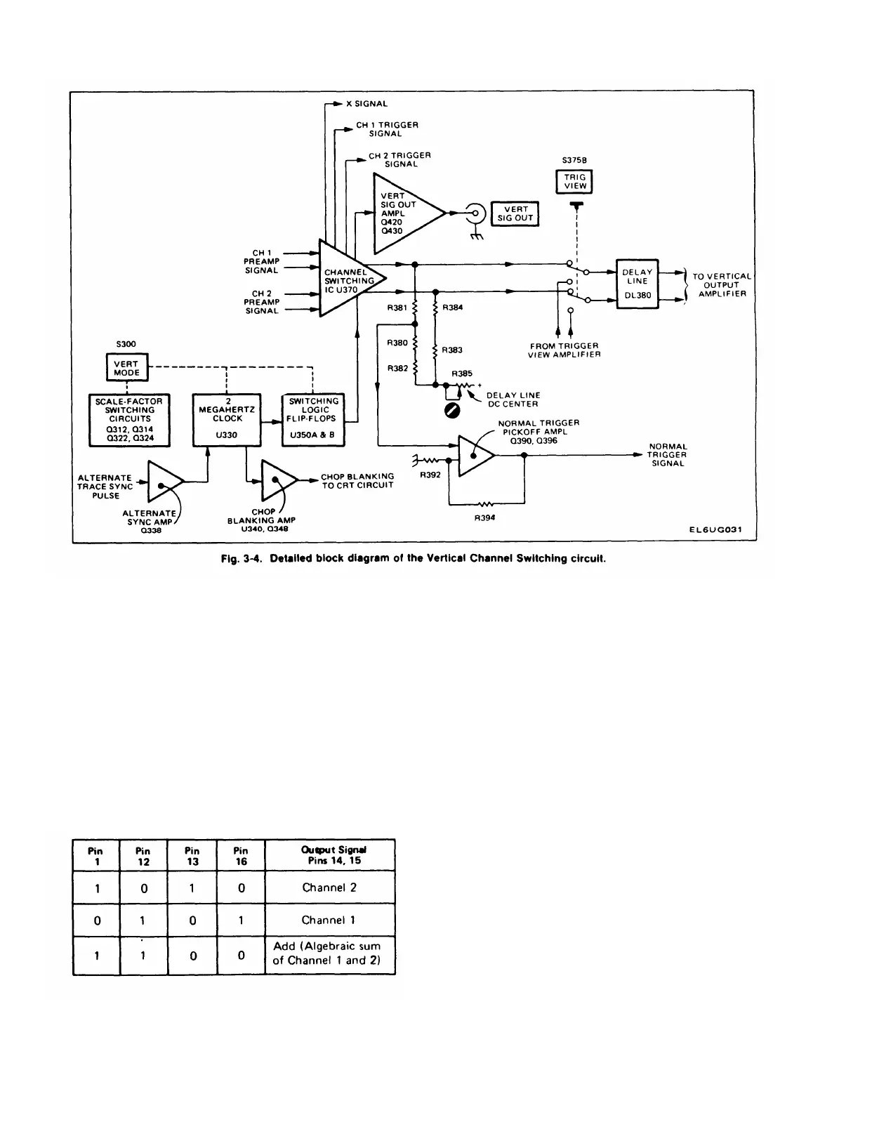
The Channel Switch IC U370 determines which of the
Preamp signals will be passed to the Vertical Output
Amplifier. The push-pull Preamp signals connect between
pins 2 and 3 (Channel 2) and between pins 10 and 11
(Channel 1) of U370. The logic levels connected to pins 1,
12, 13, and 16 determine what signals are presented at
output pins 14 and 15. The following logic truth table
(Table 3-1) defines the switching function of U370.
TABLE 3-1
Input/Output Logic for U370
U370 also makes available samples of the Channel 1
signal at pins 8 and 9 and samples of the Channel 2 signal
at pins 4 and 5. The output signals at pins 4, 5, 8, and 9 are
always present when signals are applied to the channel
inputs regardless of the switching logic levels applied to
U370. The Channel 1 signal present at pin 9 provides drive
to the Horizontal Amplifier in the X-Y mode of horizontal
operation. The Channel 1 signal at pin 8 and the Channel 2
signal at pin 4 are used by the Trigger Generator circuits in
the appropriate positions of the Trigger SOURCE
switches. The Channel 2 signal at pin 5 connects to the
Channel 2 Vertical Signal Out Amplifier.
Switching Logic Flip-Flops
U350A and U350B are edge-triggered flip-flops that
derive the switching logic for the Channel Switch IC U370.
In the CH 1, CH 2, and ADD positions of the VERT MODE
switch the output logic from U350A and U350B is
determined by the voltage levels applied to the clear (pins
1 and 13) and preset (pins 4 and 10) inputs. In the ALT
mode of operation the flip-flops are switched by the
alternate-trace sync pulse applied to their clock inputs
through Q338 and U330B. In the CHOP mode, the clock
pulse generated by U330C and U330D switch the flip-flops
at a one-megahertz rate.
3-8
 Loading...


